background image

Capacitive  touch  is  very  sensitive  to  power  noise.  Ripple
voltage/current  from  the  power  adapter  will  cause  the  LCD
ripples, and will also cause the capacitive touch malfunction:
If you use the APK Multi-Touch under Android to test, you can
find the touch point float. There are several ways to solve
this problem:

1)    Use  a  high  quality  power  adapter.  Or  use  battery  to
provide the power like cell phone or tablet PC. 

2)    If  user  power  adapter  can’t  be  good  enough,  there’s
another effective method to solve this problem: Make sure the
CS19108F215P-C111 power input connector 

Pin 3 really connect

to user “Power System Ground”

. This method can eliminate the

problem totally. User can also use another method to test this
problem: touch the GND of CS19108F215P-C111 by one hand, the
other hand operates on the capacitive touch screen. In this
case, user’s body acts as the Power System Ground.

DB9 Connector

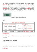
The product CS19108F215P-C111 has 4*DB9 connectors configured
as  RS232  by  default.  as  Figure  5  shows  .COM3/COM4  can  be
customized to RS485. If you need any other setting different
to the default setting, please 

contact us

.

Summary of Contents for CS19108F215P-C111

Page 1: ...PPC A9 215 C User Manual Release 2 0 Chipsee Products Naming Rules CS19108F215P C111 CS Chipsee Product Abbreviate...

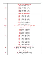
Page 2: ...4 Pixel 108 Means 1080 Pixel F T Product based on Freescale TI CPU 215 LCD Dimension 050 Means 5 0 Inch 070 Means 7 0 Inch 080 Means 8 0 Inch 097 Means 9 7 Inch 101 Means 10 1 Inch 104 Means 10 4 Inch...

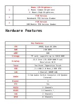
Page 3: ...Key Features CPU iMX6Q Quad A9 1GHz RAM 2GB DDR3 eMMC 8GB Storage TF card supports up to 32GB SDHC Display 21 5 Inch LCD 1920 1080 Pixel Resolution 16 9 Touch Ten Point Capacitive Touch USB 2 x USB 2...

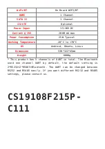
Page 4: ...perature 20 C to 70 C OS Android Ubuntu Linux Dimension 530 322 45mm Weight 6000g This product has 5 channels of UART in total The Bluetooth used one channel UART by default the default setting is 2 R...

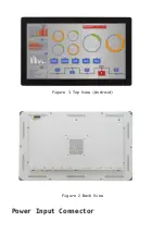
Page 5: ...Figure 1 Top View Android Figure 2 Back View Power Input Connector...

Page 6: ...system Ground Table 1 has detailed descriptions about the connector definition Figure 3 Power Input Connector Table 1 Power Input Pin Definition Pin Number Definition Description Pin 1 Positive Input...

Page 7: ...gh there s another effective method to solve this problem Make sure the CS19108F215P C111 power input connector Pin 3 really connect to user Power System Ground This method can eliminate the problem t...

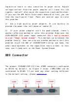
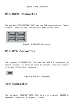
Page 8: ...current each Figure 5 USB HOST Connector USB OTG Connector The product CS19108F215P C111 has one USB OTG connector as Figure 6 shows It works as slave by default User can connect it to host PC by thi...

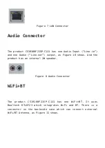
Page 9: ...ne out output as Figure 10 shows And the product has an internal 2W speaker Figure 8 Audio Connector WiFi BT The product CS19108F215P C111 has one WiFi BT It uses Realtech RTL8723 which integrates WiF...

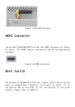
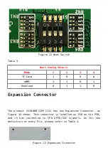
Page 10: ...2 shows The HDMI output resolution can be configured by software Figure 10 HDMI Connector Boot Switch The product CS19108F215P C111 has a boot switch which can be used to change boot sequence as Figur...

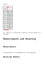
Page 11: ...ownload 0 1 1 0 Expansion Connector The product CS19108F215P C111 has one Expansion Connector as Figure 12 shows This connector is labelled as P28 on the PCB and it has connected to CPU GPIO I2C signa...

Page 12: ...PUT2 Pin 6 OUTPUT3 Pin 5 OUTPUT4 Pin 4 INPUT1 Pin 3 INPUT2 Pin 2 INPUT3 Pin 1 INPUT4 ATTENTION All signals are optocoupler isolated VCC_ISO supports 5V 24V input Measurements and Mounting Measurements...

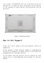
Page 13: ...ounting Method How to Get Support Please feel free to contact us with any questions queries or suggestions If your question is about technical support or troubleshooting for one of our products we kin...

Page 14: ...Mouser Electronics Authorized Distributor Click to View Pricing Inventory Delivery Lifecycle Information Chipsee CS19108F215P...

Reviews: