www.chipsee.com
6
CS19108R156P-C111
User Manual (1.0)
Power Input Connector
The product CS19108R156P-C111 uses a wide range power input:
DC 15~36V
. The total power consumption
is about
15W
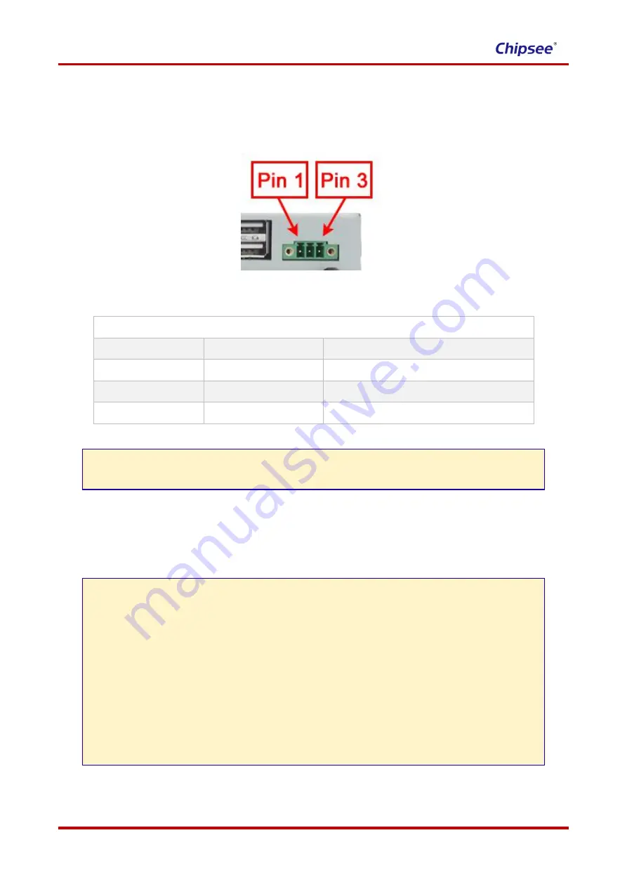
normally. The Power Input Connector is 3 Pin 3.81mm Screw Terminal Connector as Figure 3
shows. The Character
“
+
” means power
Positive
input, The Character
“
-
” means power
Negative
input. The
Character
“
G
” means system Ground. Table 1 has detailed descriptions about the connector definition.
Figure 3 Power Input Connector
Table 1
Power Input Pin Definition:
Pin Number
Definition
Description
Pin 1
Positive Input
Connect to DC Power
Positive Terminal
Pin 2
Negative Input
Connect to DC Power
Negative Terminal
Pin 3
Ground
Connect to
Power System Ground
BE ATTENTION:
The system ground
“G”
has been connected to power negative
“-”
on board.
Capacitive Touch
The product CS19108R156P-C111 uses ten-point capacitive touch.
BE ATTENTION:
Capacitive touch is very sensitive to power noise. Ripple voltage/current from the power
adapter will cause the LCD ripples, and will also cause the capacitive touch malfunction:
If you use the APK Multi-Touch under Android to test, you can find the touch point float.
There are several ways to solve this problem:
1) Use a high quality power adapter. Or use battery to provide the power like cell
phone or tablet PC.
2) If user power adapter can
’t be good enough, there’s another effective method to
solve this problem: Make sure the CS19108R156P-C111 power input connector
Pin 3
really connect to user
“Power System Ground”
. This method can eliminate the
problem totally. User can also use another method to test this problem: touch the GND
of CS19108R156P-C111 by one hand, the other hand operates on the capacitive touch
screen. In this case, user
’s body acts as the Power System Ground.

