background image

67

QuanWei MACHINERY (Jiang Su)

2) The air quantity regulation system (referring to the above control system) if the customer uses
the air quantity of the system is smaller than the air supply quantity of the air compressor, then the
air quantity regulation system can automatically adjust the air supply quantity of the air compressor.

Set the pressure of the pressure stabilizer valve makes the system before the pressure rise to

reduce the load pressure, a small amount of air will enter the servo cylinder of the intake valve
through the steady pressure valve to push the butterfly valve, and begin to adjust the air volume.
The setting pressure of the pressure-stabilized valve can be determined by the air volume used in
the field.

If the air volume is adjusted, the locking nut of the steady pressure valve will be loosened, the

counterclockwise rotation of the handle of the steady pressure valve will reduce the setting pressure,
and the clockwise rotation will increase the set pressure. After setting, tighten the lock nut.

If you do not need to adjust the volume of air, you can turn the steady pressure valve

clockwise to the limit and lock it.

6.4 Adjustment of safety valves

The discharge pressure of the relief valve is generally set to be higher than the exhaust pressure

of 0.1 Mpa. It has been adjusted well before leaving the factory, so it is not necessary to readjust it.
If you have to adjust the exhaust pressure of the relief valve for other reasons, you can relax the
locking nut above the relief valve, and then adjust the adjustment screw. If you rotate clockwise,
the exhaust pressure will increase, and the pressure set will decrease if you rotate counterclockwise.
After setting the discharge pressure, tighten the locking nut.

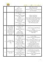
6.5 Replacement steps of oil separator

1) After the air compressor stops, the air outlet is closed and the drain valve is opened to confirm
that the system is free of pressure.
2) Disconnect the pipeline above the oil barrel and remove the pressure maintenance valve outlet
to the cooler.
3) Remove the fixing bolts above the oil and gas barrel.
4) Take away the upper cover of the oil and gas barrel and expose all the filter elements on the
barrel body.

Summary of Contents for Quan Wei

Page 1: ...TaiWan QuanWei Screw type air compressor Using and Maintenance Instructions ...

Page 2: ...ine can be used safely reliably and durably the operation and maintenance personnel are requested to read the instructions carefully before the operation of the unit Fully grasp the operational norms and skills of the air compressor group so that the air compressor in good working condition for a long time If you have something do not understand the contents in this manual please contact us as soo...

Page 3: ...l mark the warning signs such as overhaul or no closing at the power supply 6 When the unit is in operation do not loose remove any pipe accessories joints and devices The unit is filled with high pressure and high temperature liquid and gas which can cause serious personal injury accident 7 The compressor cannot work under the exhaust pressure specified by the nameplate otherwise the motor will b...

Page 4: ...ompressor 1 2 0 Air compressor installation 3 3 0 System flow and function of each part 6 4 0 Operating 17 5 0 Intelligent controller 20 6 0 Maintenance and inspection 65 7 0 Maintenance and troubleshooting 70 8 0 Performance parameters 74 9 0 Circuit diagram 82 ...

Page 5: ...mpressor is reduced In addition the lubricating oil can also reduce the noise generated by high frequency compression 1 2 Block structure of Screw Air Compressor 1 2 1 Basic structure The company uses a screw type air compressor is a two axis volumetric type of compressor The air inlet is opened at the upper end of the housing and the exhaust port is opened at the lower part some of the air ends a...

Page 6: ...he screw compressor does not have an intake and exhaust valve set The intake is only regulated by the opening and closing of a regulating valve When the rotor rotates the tooth groove space of the main and secondary rotor is the largest when it is turned to the inlet wall opening At this time the tooth groove space of the rotor is connected with the free air of the inlet because the air of the too...

Page 7: ... between the meshing surface of the two rotors and the exhaust port of the housing is zero that is to say the complete exhaust process at the same time the length of the tooth groove between the rotor meshing surface and the inlet of the housing reaches the longest and the suction process is going on again See figure 4 Figure 1 Figure 2 Figure 3 Figure 4 2 1 Installation 2 0 Air compressor Install...

Page 8: ... air should be low the dust is less and the air is clean and well ventilated 2 1 5 The ambient temperature shall be less than 45 degrees Celsius because the higher the ambient temperature the less air the air compressor will output 2 1 6 If the environment of the factory is poor and the dust is high the service life of the air compressor system parts should be maintained by installing the pre filt...

Page 9: ...of the gas Lower temperature and less moisture content can reduce the load of the dryer by re entering the dryer 7 If the air consumption of the system is very large and the time is very short it is best to add an air storage tank as a buffer which can reduce the number of empty loads of the air compressor which is of great help to the air compressor 8 For compressed air under the system pressure ...

Page 10: ...compressor to jump off because of the high temperature Cooling towers need to be easy to dissipate have good ventilation and must be fixed to prevent them from tilting 3 The water pressure of cooling water shall generally be maintained between 0 15 0 25MPa No greater than 0 4Mpa 4 The cooling water outlet temperature should be kept below 40 C and the temperature difference between incoming and out...

Page 11: ...nd the safety of repair and maintenance 2 3 4 The correctness of the voltage of the air compressor should be confirmed when it is distributed 2 3 5 The ground wire of the motor or system should be erected and the ground wire can not be directly connected to the air or cooling water pipe 2 3 6 Under normal circumstances the three phase AC motor is overloaded and the current must not exceed 10 of th...

Page 12: ...8 ...

Page 13: ...a red line in the air filter clogging or contamination indicator it means that the air filter must be cleaned or replaced B Intake valve a When starting the intake valve is in the closed state which makes the compressor start under low load lightens the load of the motor when starting and is convenient for the normal operation of the motor At the same time the inlet valve body has no air intake ho...

Page 14: ...for more details 6 Safety valves When the system pressure is set improperly or out of order the pressure inside the oil and gas barrel is higher than 0 1Mpa than the set exhaust pressure the safety valve will jump away so that the pressure will drop below the set exhaust pressure The safety valve has been adjusted before leaving the factory Please do not adjust it at will 7 Discharge valve The rel...

Page 15: ... remove the moisture oil droplets and impurities condensed after air cooling The compressed air is slightly opened through the regulating valve under the air water separator to make the condensed water flow out without causing a large amount of air leakage The company s products have automatic drainage and manual drainage for the user to choose 3 2 2 Lubricating oil flow description Because of the...

Page 16: ...erence indicator light is on the oil filter stopper must be replaced After the first 600 hours of operation of the new machine the oil and oil filters need to be replaced Then it will replaced according to the light or running time of the differential pressure indicator lamp If the pressure difference of the oil filter is large and it is not replaced it may lead to insufficient oil intake and the ...

Page 17: ...re of this cooling system is 45 If the system exceeds it is possible to cause tripping such as placing the place at the edge of the high temperature boiler 2 Water cooled model The design standard of cooling water temperature is 32 so the design of cooling water circulation system must be paid special attention In particular cooling water quality must meet the general industrial water standards be...

Page 18: ...fin on the dust if the fin on the plug matter cannot blow clean had better use the clean liquid or the volume agent to clean Water cooled air compressor is generally due to cooling copper pipe fouling blockage resulting in reduced heat transfer efficiency and high temperature tripping The highest ambient temperature of air compressor design is 45 If the ambient temperature is higher the exhaust te...

Page 19: ...ll become a vacuum and the lubricating oil required for the compressor and bearing shall be ensured by the pressure difference between the compressing chamber and the oil and gas barrel 2 Full voltage motion of motor full voltage or Operation When the pressure in the oil and gas barrel gradually rises above 0 15Mpa the inlet valve is completely open so the pressure in the oil barrel increases rapi...

Page 20: ... solenoid valve is energized the intake valve is opened and the air compressor resumes heavy load operation 5 Fan start stop control After the air end starts the fan motor does not run temporarily when the exhaust temperature reaches 80 85 can be set on PLC The fan motor will start automatically When the temperature drops to 70 C the fan motor will stop running On the one hand can save electricity...

Page 21: ...ir own according to the conditions of use Do not to start the motor often cause the motor burn 3 4 2 Electric circuit The electronic control cabinet of the air compressor can be divided into two systems one is the internal control system and the other is the starting disk part The starting disk is the commonly used Y start control of general machinery soft start and Variable Frequency start can al...

Page 22: ...delay 4 1 8 Observe whether the indicator is normal or not if the unit has abnormal sound vibration oil leakage immediately press the emergency stop button stop check 4 1 9 The exhaust temperature is maintained at 75 C 90 C 4 1 10 press stop button after 10 15 seconds the motor will stop running this is to avoid the air compressor in the heavy state of direct shutdown 4 1 11 When the stop button i...

Page 23: ...pressors that are notstarted 4 3 4 If it is found that the oil on the oil level gauge cannot be seen during long term operation and the exhaust gas temperature is too high it should be shut down immediately Stop for 10 minutes to observe the oil level if insufficient when there is no pressure in the system to replenish the lubricating oil 4 3 5 There will be condensate water in the rear cooler and...

Page 24: ...valve starter disk etc to prevent corrosion 4 Replace the lubricating oil and run for 30 minutes before stopping the operation After two or three days remove the condensate from the oil barrel and the oil cooler 5 Completely drain the cooling water 6 Remove the machine to less dust and store in a dry place as much as possible 4 4 3 Reboot procedure 1 Remove plastic paper or oil paper from the mach...

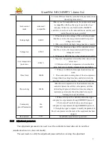
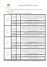
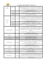
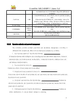
Page 25: ...put box Parameter setting and display key Page button Start Whentheaircompressorisinstandbystate pressthiskeytostart the operation of the air compressor The communication mode is set as linkage and thecommunication ...

Page 26: ...n the air compressor is running this key is used as the loading and unloading key When the display interface input focus is in the digital input box and the input box is in edit mode press this key to exit the edit mode and save the user modified data When the display interface input focus is on the page changing button press this keyto performthecorrespondingfunctionof the button Return reset Whe...

Page 27: ...the highest bit of the data begins to flicker When the focus of the display interface is in the numeric input box and indata editing mode pressthiskeytomovetheeditbittothenext bit of the current data When the focus of the display interface is on the parameter settings and display keys pressthiskeytomodifythecurrentparameterandsave it Whentheinputfocusofthedisplayscreenisonthepagechangebutton press...

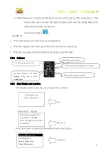
Page 28: ...eisarunparameterdisplayinterface press this key and switch to the previous page run parameter interface 5 1 2 Indicator light Power Controller charge Indicator lamp Operating Air compressor motor operating this indicator lamp Malfunction Alarm indicator twinkle and shutdown and indicator lamp always light on malfunction clear Reset and extinguish 5 1 3 State display and operation The display Contr...

Page 29: ...event dry starting and stopping it takes This icon indicates that the 0 2 seconds to perform the timing pressur e function is on This icon This icon indicates that the corresponding function indicates that the remote computer monitoring function is turned on After a delay of 5 seconds the following run parameter interface is displayed The user clicks the menu ammonium button on the display interfa...

Page 30: ... output frequency 000 0 Hz Display current motor Frequency converter output frequency Motor output electricity 000 0 A Display current motor Frequency converter output electricity Motor output voltage 000 0 V Display current motor Frequency converter output voltage Motor output Power 000 0 Kw Display current motor Frequency converter real time output Power Motor Electricity consumption 0000000 0K ...

Page 31: ...city consumption 000000 00K w H Display controller according to the Fan motor Frequency converter output real time Power total Electricity consumption Fan motor total Electricity consumption 000000 00K w H Display controller according to the Fan motor Frequency converter output real time Power total Electricity consumption Fan motor state 0000 Controller obtained by Fan motor Frequency converter r...

Page 32: ... is closed the circle color in the output port state is red and when the terminal is broken the circle color in theoutput port state is light red Power frequenc y motor UI 000000 0Kw Display controller sample by the motor real time electricity and real time voltage product Power frequenc y motor Electricity consumption 0000000 0Kw H When the model is power frequency the power consumptionof the mot...

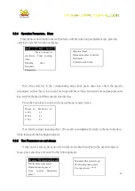
Page 33: ...n the password validation interface Key operation 1 when data view mode press left or right shift key enter data edit mode 2 Data view mode work press the move down or up key move the current focus to the next component 3 When data editing mode the current bit data is modified by moving up and down key 4 In data editing mode press the left or right shift key to move the modifier bit to the next da...

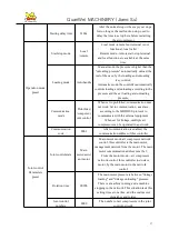
Page 34: ...tart delay time Loaddelaytime s 0002 After the motor angle runs the delay loading time Empty load delay time s 0600 Air compressor allows the longest continuous no load operation time after this time automatically stop running into the empty car too long stop state Shut down delay time s 0010 Whennormalshutdown theaircompressorimmediatelyno load operation noloadoperationthissettingtimeafter the st...

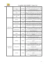
Page 35: ...Adjust the back brightness the higher the value the strongerthebrightness Adjustablebrightnessof1 7 Communication mode Prohibition linkage computer Whenitissettobeprohibited communicationdoesnot work Set to communication as slave according to the MODBUS RTU protocol to communicate with the external equipment baud rate 9600 dataformat 8N1 checkbit evencheck When set for linkage multiple air compres...

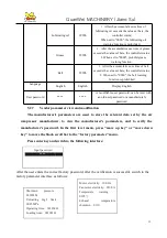
Page 36: ...aximum allowable overload of wind motor value 1 2 The current of wind motor is more than 1 2 times of the set value Exhaust warning temperature 0105 Warning if exhaust temperature is higher than this set temperature Exhaust stop temperature 0110 Failure stop when exhaust temperature is higher than this set temperature Front bearing warning temperature 0105 When the temperature of the front bearing...

Page 37: ... set to 0000 the high voltage function is invalid Voltage low V 0350 Whenthedetectionvoltageof thecontrollerislower thantheset value thestopprotectionandthereported voltage are too low When set to 0000 the low voltage function is invalid Communication timeout s 002 0 The timing starts when the controller sends the first byte and if no response from the converter is received within this time the co...

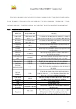
Page 38: ...uency fan Frequency 50HZ 60HZ Set the power frequency Oil pressure differential warning MPA 00 15 When the pressure of air compressor is higher than 0 5Mpa The system detects the pressure exhaust pressure pipeline pressure resistance pressure differential warningvalue Oil pressure difference stop 00 20 When the pressure of the air compressor is higher than 0 5 Mpa When the pressure of the air comp...

Page 39: ...800 2 000 Temperature value detection temperature value temperature coefficient Temperature2Coeffic ient 1 000 NOTE MAM6080 controller Spare Temperature3Coeffic ient 1 000 Temperature4Coeffic ient 1 000 Temperature5Coeffic ient 1 000 Temperature6Coeffic ient 1 000 Pressure1Coefficient 1 000 Used to calibrate the supply pressure The pressure coefficientis setintherangeof 0 800 2 000 Pressure value ...

Page 40: ...pressure range MPa 01 60 Set the controller pressure 2 sensor ranges Standby Phase sequence protection value V 000 9 When the voltage value detected by the three phase phase sequence detection circuit is lower than the value set here the phase sequence error is reported When this value is set to 0 phase sequence protection is disabled Lack of sequence protection value V 000 0 When the detected pha...

Page 41: ...structions Joint control net work Power freque ncy Power fr equency Variable Frequency Po wer frequenc y Variable Frequency Va riable Frequency Power frequency Power frequency for Power frequencyAircompressorandPower frequencyAir compressor joint control Variable Frequency Power frequency for Variable Frequency Air compressor and Power frequency Air compressor joint control Variable Frequency Vari...

Page 42: ...e parameter Consumable parameters are used to set consumption time The user needs to verify the consumables password before viewing or modifying the consumable parameters The main functions and functions are shown in the table below Menu Setting initial value Function description Oil filter using time h 0000 Theoilfilterhasbeeninuseforacumulativeperiodoftime after replacing the new oil filter manu...

Page 43: ...ofgreaseexceedsthevalue set here the controller warns 2 When set to 0000 prohibit grease warning function 5 1 11 Frequency converter preset The frequency converter is preset for setting the frequency converter parameters User view or modify the frequency converter preset before the need to verify the frequency converter preset password The main functions and functions are shown in the following ta...

Page 44: ...rter manual and communication section Write frequency address 2136 Frequency converter communicates the corresponding register address of given frequency Frequency Calculate value 0001 0001 The calculated value is a frequency value with one decimal place For different frequency converters the formula is converted to the corresponding data and sent to the frequency converter For example the control...

Page 45: ... Frequency converter voltage address Voltage Display receive 000 1 0001 Calculate the voltage formula of frequency converter The controller converts the read voltage to 1 decimal place data Electricity address 0C84 Read Frequency converter electricity address Electricity Display receive 000 1 0001 The formula of frequency converter current is calculated The controller converts the read current int...

Page 46: ...imeisbetweenthepressurestarttimeand thepressure endtime thepressureishigherthanthis setting value to unload Variable Frequency operating pressure MPa 00 70 When the time is between pressure start time and pressure end time the supply pressure is set when the Variable Frequency air compressor is running stably When thepressurefluctuatesnearthepressure the controller adjusts the frequency of the fre...

Page 47: ...he pressure fluctuates near the pressure the controller adjusts the frequency of frequency converter so that the pressure of supply gas is close to the value set here This parameter only works when the motor is variable frequency or the fan motor is variable frequency Motor rising rate 1000 When PID is adjusted it is used to limit the increment of the result of each PID operation To prevent the op...

Page 48: ...e fast and slowly and determines the steady state error the value big tracking fast the steady state error small the value small tracking slowly the steady state error big Motor Differential gain 0000 It is mainly used for lag tracking of large delay systems such as temperature etc generally not required and set to 0000 Motor frequency Upper limit HZ 050 0 Maximum operating frequency of air compre...

Page 49: ...disconnected the main frequency converter operation terminal is disconnected and the frequency converter slows down according to the set deceleration time Free stop when the stop mode in the factory parameter is set as free stop the controller receives the stop order the loading valve disconnects the operating terminal of the main engine frequency converter remains closed and the frequency of the ...

Page 50: ...bea constantpower frequency 1 setting value at most ConstantPowerpressur e2 MPa 0 70 For constant power operation when the detection pressureis greaterthanorequaltothesetvaluehere theoutputfrequencyis allowedtobea constantpower frequency 2 setting value at most ConstantPowerpressur e3 MPa 0 80 For constant power operation when the detection pressure is greater than or equal to the set value here t...

Page 51: ...y downtime delay second 0000 Set to 0 seconds low frequency function is invalid Note1 Constant Power controlling ConstantPowerpressure1 constantPowerpressure2 constantPowerpressure3 constantPower pressure4 constantPowerpressure5 constantPowerpressure6 constantPowerpressure7 Note2 ConstantPowerfrequency1 constantPowerfrequency2 constantPowerfrequency3 constantPowerfrequenc y4 constantPowerfrequency...

Page 52: ...anorequal to this value the output frequency of the wind motor Frequency converter is controlled which the upper limit value of the frequency is set in the manufacturer s parameters Thisparameteronlyworks when the model is set to be variable frequency of the wind motor or the fan motor is variable frequency Fan motor Rising rate 1000 When PID is adjusted it is used to limit the incrementofthe resu...

Page 53: ...e integral range the integral is calculated with this set value Fan motor Integral range 0005 set Variable Frequency working temperature integral range Detection temperature set Variable Frequency working temperature integral range integral gain function Outside this range the initial value of the integral works Fan motor Proportional gain 0100 Track setting working temperature fast value large tr...

Page 54: ...Operation Authority and password management The controller provides multiple passwords and permission management according to different levels of passwords different levels of operation permissions as follows 19 1User parameter password factory settings are Permissions allows all user parameters to be modified 19 2 Factory parameter password fixed to Permissions allows all user parameters to be mo...

Page 55: ...ck accuracy 19 9 Timing pressure codes Permission allows all timing pressure parameters to be modified 19 10 Time start stop password Permission allows modification of all time start and stop parameters 19 11 Main motor Variable Frequency codes fixed as Permissions all settings in the main motor Frequency converter are allowed to be modified 19 12 Fan Variable Frequency code fixed as Permission al...

Page 56: ... theequipment isin downtime long press the stop buttonto displaythe software version information Load unloading confirm 1 This key acts as the loading and unloading key while the air compressor is running 2 When setting the mode press this key to confirm and save the input data Down decline 1 When viewing the parameter press this key to move the scroll bar down 2 Whenyoumodifydata pressthiskeytode...

Page 57: ...eset the fault 5 2 2 Indicator Air filter using time on alert Motor Power supply fault Exhaust temperature high time and exhaust Oil filter indicator Oil filters plugging using time to early warning light Oil separator using time on alert 5 2 3 State Display and operation The Display interface after the unit is turned on is as follows View Delay time5s Display Main view Press move down to enter th...

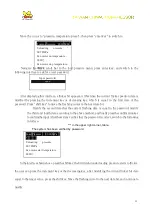
Page 58: ...such as main fan current moving scroll bar to main fancurrent menuitem pressenter key switchtothemainandfancurrentvalue interface Press the return key to return to the parent menu or main screen If an interface stops operating after 120 seconds to automatically return to the main interface while turning off the backlight indicator 5 2 5 User Parameters see and change On the one level menu press up...

Page 59: ...sing key which is equal to the first data of the password Press shift key to move the flashing cursor to the next data bit Modify the second data that the current flashing data is equal to the password modify the third and fourth data according to the above method andfinallypresstheconfirmationkey toconfirmtheinput Afterthesystem verifies that the password is correct switch to the following interf...

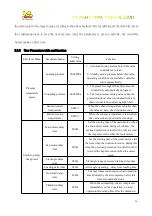
Page 60: ...ture is higher than the value set here the wind motor runs Fan motor stop temperature 0070 When the exhaust temperature is lower than the value set here the wind motor stops Start stop delay time preset Main motor delay time 0008s Set the starting time of the main motor when the main motor starts during which time the overload protection is invalid in order to avoid the impulse current when the mo...

Page 61: ...cation does not work Set to communication as a slave according to the MODBUS protocol to communicate with the external equipment When set for linkage multiple air compressors can be operated in a network Communication code 0001 After communication is enabled the communication address of this controller Joint control Parameters preset Joint control state Main motor assist ant motor Main motor mode ...

Page 62: ...ter accumulates the time used after replacing the new air filter manually clear the zero Lubricating oil 0000h The lubricating oil accumulates the usage time after replacing the lubricating oil in the manual clearing zero Grease 0000h Grease has been used for a cumulative period of time after replacing the grease in manual clearance Belt 0000h Belt accumulative usage time replace the new belt afte...

Page 63: ...sword can be reset with an old user password or a manufacturer s password 5 2 7 Vendor parameter view and modification The manufacturer s parameters are used to store the relevant data set by the air compressor manufacturer to view the manufacturer s parameters and to verify the manufacturer s password In the first level menu press move up key or move down key to move the black scroll bar to the f...

Page 64: ...When the gas supply pressure is higher than this set pressure the fault stops Unloading high limit 0 80MPa This is the maximum unload pressure in the user parameter and the unloading pressure set here Running time 000100h Modify the total operating time of the air compressor Load time 000095h Modify the total load time of the air compressor Historical malfunction reset Enter 8888 and after confirm...

Page 65: ... stop indicating temperature sensor failure Time limit 0000h 1 When set to 0000 the time span function does not work 2 The accumulative running time of the air compressor is larger than the setting time here and when it is in the downtime state it will report the wrong use shutdown Pre warning 0010h When the air compressor is in the downtime state the controller detects the oil filter oil separato...

Page 66: ...librating the current the input coefficient Controller display current value sampling value coefficient Current electricity A Current real time electricity value Motor C phase Standard electricity 0000 1 It is used to calibrate the C phase current of the motor After the standard current value is input the controller automatically calculates the current coefficient and saves it to complete the curr...

Page 67: ...e the controller automatically calculatesthe temperature coefficient and saves it to complete the temperature calibration 2 After the calibration is completed the standard temperature value is automatically returned to zero Coefficient 1 000 Input coefficient when calibrating temperature The controller displays the temperature value sampling temperature value zero point coefficient Zero 0010 Compe...

Page 68: ...swords and permission management according to different levels of passwords different levels ofoperation permissions as follows 1 User operator password fixed for the following Permissions allowtomodifyloadingpressure unloadingpressure fanmotorstart temperature fan motor stop temperature start and stop mode loading mode communication mode communication code and linkage related parameters 2 User pa...

Page 69: ... grade lubricating oil of QuanWei screw air compressor to ensure the service life of the main engine 6 1 2 Reasons for affecting the time of oil exchange 1 Poor ventilation Environmental temperature too high 2 High humidity environment and rainy season 3 Dusty environment 4 Different oil mixture 6 1 3 Oil exchange steps 1 The air compressor is operated to increase the oil temperature and facilitat...

Page 70: ...l decline It is also easy to form oil spontaneous combustion and the event of air compressor burning 3 After two years of operation the air compressor had better do a system cleaning with lubricating oil The method is to replace the lubricating oil immediately after the air compressor has been running for 6 8 hours when the new lubricating oil is replaced The residual organic components of the ori...

Page 71: ...r setting tighten the lock nut If you do not need to adjust the volume of air you can turn the steady pressure valve clockwise to the limit and lock it 6 4 Adjustment of safety valves The discharge pressure of the relief valve is generally set to be higher than the exhaust pressure of 0 1 Mpa It has been adjusted well before leaving the factory so it is not necessary to readjust it If you have to ...

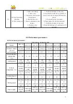
Page 72: ...st once a week Inspection should be conducted on a daily basis when necessary During maintenance be careful not to let dirt into the clean side of the air filter 6 6 1 Maintenance of air filters Air filters must be cleaned intermediate or replaced with new air filter cores see guidelines for intermediate cleaning 6 6 2 Intermediate cleaning of air filters Do not wash in the middle more than five t...

Page 73: ...ilters should not be installed when wet 6 6 3 Check the damage to the air filter Before installing a cleaned air filter it must be placed in front of a bright light source portable lamp and checked strictly for cracks holes and other damage At the same time the airtight should also be checked 6 6 4 Duration of replacement of filters and separators Operating conditions such as coolant temperature o...

Page 74: ... 3 Every 1000 hours of operation 1 Check the intake filter core or replace it 7 1 4 For every 2000 hours or 6 months of operation 1 Checking the lines of each department 2 Inspect the lubricating oil and determine whether it is effective or replaced 3 Inspect the oil mirror and remove the cleaning 7 1 5 For every 3000 hours or year ofoperation 1 Clean inlet and emptying valves 2 Check three phase ...

Page 75: ... replace the electrical personnel 4 Please replace the electrical personnel 5 Please replace the electrical personnel 6 Please replace the electrical personnel 7 Manual body if you can not turn please takes a phone call to us 8 Check power cord and contacts 9 Troubleshooting or replacing afterchecking field faults in operation parameters 2 High running current compressor tripping Voltage is too lo...

Page 76: ...bricating oil Temperature control valve failure The air filter is not clean Oil filters blocking Cooling fan fault Intake pre filtration blockage If the oil level is below L please stop to refuel to H Check the temperature difference between the inlet and outlet pipes Check the inlet temperature Increase exhaust air and reduce room temperature Check the inlet and outlet tubing temperature differen...

Page 77: ...age Pressure sensor failure Remove and clean and add lubricating grease Maintenance and replacement if necessary Overhaul and replacement Replacement 9 Compressor air volume below normal value 1 Intake filter blockage 2 Air intake valve bad operation 3 Poor operation of pressure maintenance valve 4 Oil separator clogging 5 Drain valve leakage 6 The setting of the stabilizer valve is wrong 7 Increa...

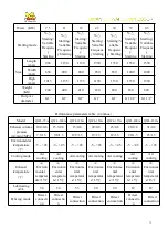
Page 78: ...essure m3 min MPA 1 1 0 8 1 6 0 8 2 2 0 8 3 5 0 8 5 0 0 8 6 1 0 8 7 7 0 8 0 8 1 3 1 2 1 3 1 7 1 3 2 9 1 3 3 9 1 3 5 1 1 3 5 9 1 3 Environmental temperature 5 45 5 45 5 45 5 45 5 45 5 45 5 45 cooling mode Air cooling Air cooling Air cooling Air cooling Air cooling Air cooling Air cooling Exhaust temperature Environ mental temperat ure 15 Environm ental temperatu re 15 Environ mental temperat ure 15...

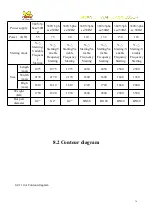
Page 79: ...Model QWL 75A QWL 100A QWL 120A QWL 150A QWL 175A QWL 200A QWL 250A Exhaust volume pressure m3 min MPA 10 0 0 8 13 3 0 8 15 0 8 20 0 8 23 0 8 26 0 8 31 0 8 7 5 1 3 9 8 1 3 12 3 1 3 15 1 3 18 1 3 20 1 3 25 1 3 Environmental temperature 5 45 5 45 5 45 5 45 5 45 5 45 5 45 Cooling mode Air cooling Air cooling Air cooling Air cooling Air cooling Air cooling Air cooling Exhaust temperature Environ menta...

Page 80: ... Starting Va riable Frequency Starting Y Starting Va riable Frequency Starting Y Starting Va riable Frequency Starting Y Starting V ariable Frequency Starting Y Starting V ariable Frequency Starting Size Length mm 1975 1975 1975 2450 2450 2540 2900 Width mm 2170 2170 2170 1600 1600 1640 1960 High mm 1610 1610 1610 1720 1720 1860 2000 Weight KG 1750 1820 1930 2600 2800 2900 3500 Out port diameter G...

Page 81: ...77 ...

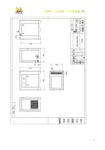
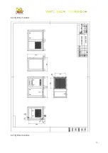
Page 82: ...78 8 2 2 QWL 15A 20A 8 2 3 QWL 30A 40A ...

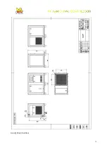
Page 83: ...79 8 2 4 QWL 50A 60A ...

Page 84: ...80 8 2 5 QWL 75A 100A ...

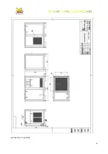
Page 85: ...81 8 2 6 QWL 150A 175A ...

Page 86: ...82 9 0 Circuit diagram ...

Page 87: ...83 9 1 MAM 860 880 Circuit diagram 9 2 MAM 890 Circuit diagram ...

Page 88: ...84 9 3 MAM 6080 Circuit diagram ...

Page 89: ...85 Screw Air Compressor operation record tale ...

Page 90: ...eration electricity A 6 Operation voltage V 7 Exhaust pressure Kg cm2 G 8 Exhaust temperature Co 9 Operation hour Record person Remark The company has the right to improve the products not the obligation to modify and improve the products Please understand TAIWAN QUANWEI MACHINERY CO LTD Tel 886 07 749 2151 3 Website www chiwai com TEL 400 6014 677 ...

Reviews: