18
be engaged, the built
–
in safety interlock mechanism will prevent simultaneous engagement of
(2) and (3).
For threading, put the lever (1) on the gear box to the right and the lead screw rotating,
then make the cross/longitudinal feed lever (2) on the middle and engage the half nut (3), the
result is the lead screw rotating and to make the carriage moving to the right and left.
CAUTION: DO NOT FORCE THE HALF NUT LEVER WHILE ENGAGING WITH
THE LEAD SCREW
When power feed, the direction of spindle rotating, carriage moving and cross
–
slide
moving nave been designed by mechanism, for example, when the spindle clockwise rotating,
the carriage move to left, conversely to right.
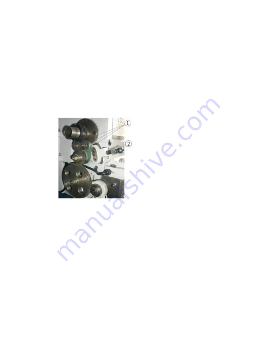
3-star gear system can change the carriage travel direction too, when the spindle clockwise
rotating and the lever (2) on up position, it make the carriage move left, the lever (2) on down
position, carriage move right. The lever (2) on middle, the carriage stop moving.
10.6.2 THREADING DIAL
When the pitch proportion of lead screw and work -piece thread is not integer times and
need to open the half
–
nut while cutting, it is necessary to use the t hread dial to control tools
and prevent the mixed screw.
The threading dial is located on the right or left side of the apron.
It performs the important function of indicating the proper time to engage the half nut lever
so that the tool will enter the sam e groove of the thread on each successive cut. The dial is
marked with lines numbered 1. 2. 3. 4. and in between are lines with no number. These are half
lines and are called unnumbered lines. The dial when engaged with the lead screw will cause the
rotation of the dial, A single line is marked on the housing of the threading dial ( fixed line ).
The instruction plate riveted on the threading dial shows the selection and sequence of
matching the revolving lines with the fixed line.
For thread cutting, engage the half
–
nuts at the appropriate numbers shown on the scale
column of the threading dial plate, 1 - 4 on the scale means the half
–
nuts can be engaged on any
of the numbered lines 1- 2
–
3
–
4 . For each successive cuts only numbered lines must be used.
1-3/2
–
4 on the scale means the half
–
nut can be engaged on 1 and 3 or 2 and 4 for successive
cuts, For example, when you engage the half
– nut on the numbered line “1” for the first cut,
after that for successive cuts, the half
–
nut just be engaged on
the numbered line “1” or “3” , If
you engage the half
– nut on the numbered line “2” for the first cut. After that for successive
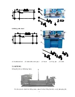
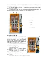
(1) 3-star gear
(2) Changing direction lever
Summary of Contents for CZ1224
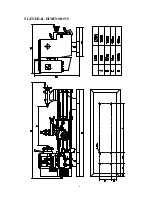
Page 7: ...6 5 GENERAL DIMENSIONS ...


