CHK Power Quality Pty Ltd, User Manual
–
Miro Power Quality Logger and Analyser, 15 August 2016
Website:
; Enquiries:
Page 18
Address:
Unit 1, 3 Tollis Place, Seven Hills, NSW 2147, Sydney, Australia;
ABN:
53 169 840 831;
Telephone:
+61 2 8283 6945;
Fax:
+61 2 8212 8105;
Website:
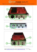
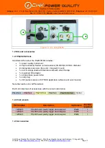
Connect the appropriate voltage lead to the Miro. The voltage connector is keyed. Screw up
the locking ring to ensure the connector does not inadvertently become disconnected.
Connect the appropriate current probes to the Miro. These connectors are keyed. Screw on
the locking rings to ensure that the connectors do not become inadvertently disconnected.
When any voltage clamp/plug is connected to a hazardous live conductor, the other voltage
clamp/plugs should also be treated as live, due to the internal measurement impedance of
the Miro.
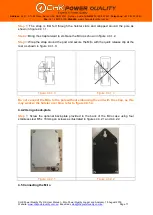
When attaching the connectors to the Miro, ensure the connectors and receptacles on the
Miro are completely dry.
To ensure accurate power measurements, it is important that the current probes are
connected to the same phases as the voltage leads. For example, the A phase voltage must
be measured by the A phase voltage clamp and the A phase current probe must measure
the A phase current. Current probe arrows should point to the load to ensure accurate power
measurement.
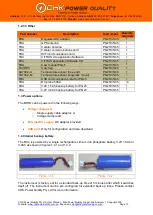
Connect the current probes first, making sure that:
They are connected to the appropriate phase; and
The arrow markings point towards the load.
PQ25/35
Connect the voltage clamps in the following order:
PC4:
Insert the plug in the GPO and switch it on;
VL4:
Neutral, Phase C, Phase B, Phase A; and
VL6:
Neutral C, Phase C, Neutral B, Phase B, Neutral A, Phase A.
PQ45
Connect the voltage clamps in the following order:
PC5:
Insert the plug in the GPO and switch it on;
VL5-C and VL5-B:
Ground, Neutral, Phase C, Phase B, Phase A; and
VL8-B:
Ground, Neutral, Neutral C, Phase C, Neutral B, Phase B,
Neutral A, Phase A.
The Miro is powered from the Phase A to Neutral connection, and will commence logging
once the A phase connection is made. It will draw power approximately 12 VA from the A
phase.
4.6 Post-installation checks
Ensure that voltage clamps and current probes are secure and not likely to move or
dislodge.
Check that all leads are secure and will not be damaged when equipment doors are
closed.


