6. Description of Communication Interfaces.
6.1 Standard COM Interface
Cool POWER offers a standard interface which makes it possible to transfer data on an RS232 seri-
al communication protocol. The same interface provides for basic signaling communication using dry
contacts.
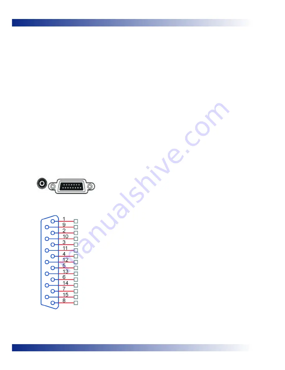
Both types of interface are combined in a 15-pin Sub-D connector with the serial communication sig-
nals, 2 output signals and 1 input signal, all with voltage levels according to the V24 standard.
The equipment comes with a communication cable with a 9-pin Sub-D connection on one end and a
15-pine Sub-D connector on the other.
Both communication systems can be used for:
· Direct communications between the UPS and the computer (PC)
· Installing the UPS is a centrally controlled network
Transferring basic operating statuses in external signaling systems
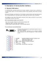
The connector pins are described below:
- The logic of the low battery and network failure signals can be con-
figured in the software.
- The “remote shutdown” input signal can be enabled or disabled
from the software and is active at logical level “1” (takes 5 seconds
to act).
21
REV: 16/03/01
Operating Manual
945012.066
1 - Low battery
: Signal that the battery’s autonomy is coming to an end
2 - TDO
: Serial communication output
3 - RDI
: Serial communication input
4 - Remote shutdown : Remote UPS shutdown input signal
5 - GND
: ground
9 - +5V @ 10mA
: 5V signal
11 – Network failure : Network failure output signal
Summary of Contents for Cool Power 1200
Page 1: ......
Page 2: ......
Page 6: ...6 945012 066 REV 16 03 01 Operating Manual ...
Page 28: ...28 REV 16 03 01 945012 066 ...
Page 31: ......
Page 32: ......


