32
Installation
Input / Output connections
When installing a multiple block parallel system, the input and output connections procedures for each module use the same
terminals as those for a single UPS. For more information refer to Chapter 3 of Owners Manual.
Parallel Communications
The individual UPS blocks communicate with each other via a 25-conductor cable. The communication cables are shielded and
must be routed separately from the power cables.
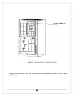
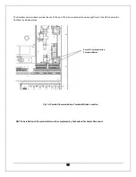
Each unit is equipped with a cable channel located in the right front of the UPS. Access to this channel is from the top or bottom
depending on the type of installation. (See chapter 3 figure 5). Route the communication cables through the cable channel to the
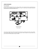
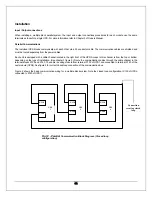
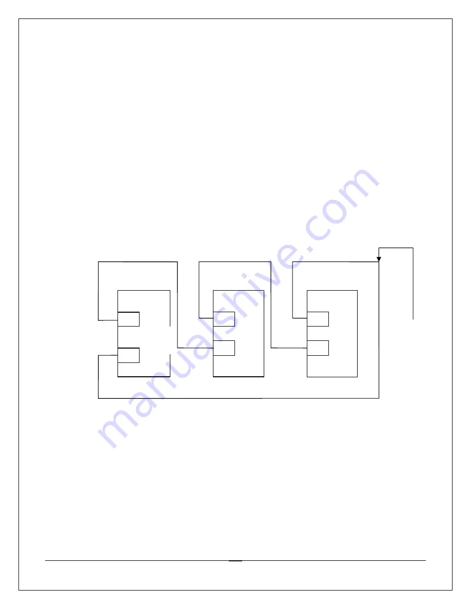
terminal blocks X130 and X140. The cable is exiting module from terminal X130 of UPS1 and connected to terminal X140 of the
next module (UPS2). See figure 2 for correct closed loop connection of the communication bus.
Figure 2 shows the basic communication wiring for a multiple block system. Note the closed loop configuration. (X130 of UPSn
connected to X140 of UPS1).
X140
X140
X130
X130
X140
UPS
2
UPS
n
Connection
creating closed
loop
Fig 12 - Parallel
Communication Block Diagram. (Closed loop
configuration)
UPS
1
X130

