Chapter 3 Installation
22
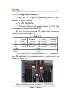
(4) Make sure all cables are tightened on L1, L2, L3 and
ground terminals properly.
3.3.3 Communication connection
(1) RS485 communication connection (Standard
configuration)
:
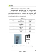
The LCD board on the inverter has 2 RJ45
communication connectors, which are RS485-1 and
RS485-2, as shown in Figure 3-14.
Ethernet
RS485-2
RS485-1
Figure 3-14 Signal cable terminals for communication
(2) The communication of one single local inverter can
be connected from the RS485-1 or RS485-2 port on the
inverter to 485 bus bar directly.
(3) For remote monitoring of more inverters, connect the
RS485-1 port of one inverter to the RS485-2 port of another
inverter and then connect to the data logger (Interlink)
through the 485 bus bar to send data to the background
monitoring system. For more information, please refer to the
User Manual of Interlink.


