Chapter 2 Overview
6
breaker, DC EMI filter, inverter unit and then remove the high
frequency component with the output sine wave filter. The
two strings of current will be connected in parallel after going
through Level 1 AC circuit breaker and be transferred to AC
EMI circuit and breaker, then finally be fed to the power grid.
The basic schematic diagram of CPS SC250KTL-H inverter
is shown in Figure 2-3.
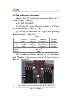
Figure 2-2 Schematic diagram of CPS SC500KTL
Figure 2-3 Schematic diagram of CPS SC250KTL-H


