er
r
w h s
V i
PV i
2
.
4
.
1
Basic principle Description
2
.
4
.
2
Circuit Diagrams
The 3K-6
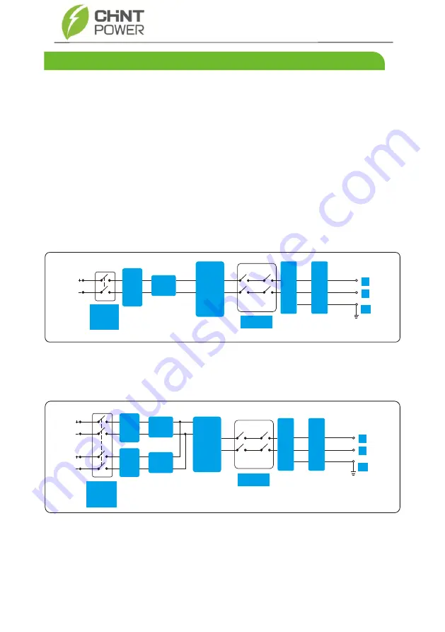
nverter with 2 MPPT input receives inputs from two strings of PV panel
(1K-3.6K P
nve t
it
ingle MPPT input receives inputs from only one sting of PV
panel). Then the inputs are grouped into two independent MPPT routes inside the
inverter to track the maximum power point of the PV panel. The two MPPT power is
then converted into DC Bus, then the DC power is converted to AC power through an
inverter circuit. Finally the AC power is fed to the power grid. EMI filer is used on both
the DC and AC sides to reduce the electromagnetic inference; Surge protection is
supported on AC side.
Figure 2.8 shows the circuit diagram for the 1K-3.6K PV Inverter with Single MPPT Input
:
Figure 2.9 shows the circuit diagram for the 3K-6K Inverter with 2 MPPT Input
:
Figure 2.8 circuit diagram
Figure 2.9 circuit diagram
DC
EMI
Filter
1
MPPT
Route
In
v
e
rt
e
r c
ir
c
u
it
AC EMI Filter
Relay
L
N
PE
AC surge
protector
PV DC
Switch
DC
EMI
Filter
1
MPPT
Route1
Inverter circuit
AC EMI Filter
PV DC
Switch
Relay
L
N
PE
MPPT
Route2
AC surge
protector
DC
EMI
Filter
2
9
2
.
4
Working Process
CPS SCA-S/
SM Series Inverter


