background image


561105-10 en ma 2012.10 

7/22

The machine is of the attended type, and must be installed in 
places where it can be monitored by trained personnel.

Warning: it is forbidden to install the machine in a place where 
it may be reached, touched and/or operated by persons other 
than those specified in section “1.2. - Authorized persons”.

The machine may only operate in places with an ambient temperature ranging 
between 10°C (50°F) and 32°C. (89,6°F).

5.1. Accessories supplied

•  Pipe cleaner: for correct cleaning of the hot chocolate dispensing channel.

5.2. Installation-Positioning

It is necessary to check the following:
•  the site has been duly prepared for machine installation;

• 

that the premises are suitably well lit, aired, clean and hygienic, and that the 
power socket is within easy reach;

•  the surface the machine will be installed on is firm, flat and solid;

• 

that the machine is placed at least 20 cm (7.8 inches) from the edge of the 
top used.

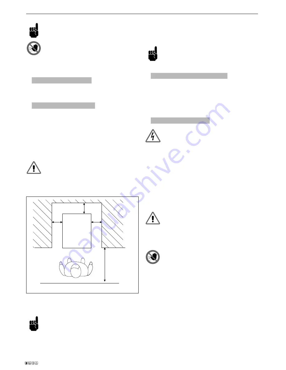
Adeguate clearance must be left around the machine to enable 
personnel to work without any constraints and also to leave the 
work area immediately in case of need.

Fig. 5 shows the minimum clearances for installation.

Note: Leave a 25 cm (10 inches) space in the upper part.

Fig. 5 shows the clearances required for access:
•  the controls situated on the left side;
•  machine parts so that they may be serviced in the event of a fault.

Important note: when lifting the machine, do not use the prod-
uct dispenser unit (tap), drainage pipe, water level indicator 
tray, bowl hook on handles or the bowl itself; grip the bottom 
machine body.  Any damage to the machine deriving from fail-

ure to follow these rules will not be covered by the warranty.

After positioning the packing container in the vicinity of the installation site, pro-
ceed as follows:
•  open the front part of the packing container;
•  lift the machine and remove it from its packing;
•  then position it on the prepared site.

Before the machine is operated the first time, its components must 
be thoroughly cleaned; for further details see the relevant section 
herein.

5.3.  Disposal of packing materials

After opening the box, make sure to separate the packing materials according
to type and dispose of them in accordance with the current regulations in the
user’s country.

We recommend keeping the box for future conveyance or transport.

5.4. Electrical connection

This job may be performed only by specialized technical per-
sonnel.

Before inserting the plug into the mains power socket, make sure that:
•  the line voltage used is the same as the value indicated on the manufactur-

er’s rating plate;

•  the main switch is set to -OFF-.

If the machine is being connected to the electricity mains for the first time, this 
operation must be performed by a specialized technician, while the Customer 
will be responsible for and have to take care of any subsequent connections.

The machine must be connected to the electricity mains by means of the plug
fi tted on the power cord. Be sure to comply with:
•  the technical regulations and standards in force at the time of installation;
•  the data shown on the rating plate on the side of the machine.

Warning: the electric outlet must be situated in a place easily 
within reach of the user, so that no effort is required in order 
to disconnect the machine from the power supply when neces-
sary.

If the power cord is damaged, you must have it replaced either by the
manufacturer or a specialized technician.

It is forbidden:

• 

to use extension cords of any type;

• 

to replace the original plug;

• 

to use adaptors.

Fig. 5

150 cm
60 inches

25 cm

10 inches

25 cm

10 inches

25 cm
10 inches

Summary of Contents for 561.105 Emga

Page 1: ...1 22 HOT CHOCOLATE DISPENSER MANUAL 561 105 561 110 ...

Page 2: ...acking materials 7 5 4 Electrical connection 7 6 OPERATION 8 6 1 Starting up 8 6 2 Dispensing the product 9 7 CLEANING AND MAINTENANCE 10 7 1 Cleaning and sanitation procedures 10 7 2 Emptying the bowl 11 7 3 Removing the bowl 11 7 4 Removing the tap 12 7 5 Cleaning the pan 13 7 6 Disassembling the tap 14 7 7 Washing and sanitizing the components 15 7 8 Assembling the washed components 15 7 8 1 As...

Page 3: ... until you have read and thoroughly understood the contents of this manual 1 3 2 Who must read the manual This manual is aimed at users and specialized technicians Users must not attempt to carry out any operations restricted to qualified technicians The manufacturer will not be liable for any damage or injury caused as a result of failure to comply with this rule The instruction manual is an inte...

Page 4: ...0 V version 18 Boiler tank drainage cap 2 3 Technical Data The technical data and features are listed below Model 5 Liters 1 32 Gal US 10 Liters 2 64 Gal US Machine dimensions L x P x A L 28 75 cm 11 32 inch P 41 35 cm 16 28 inch A 46 50 cm 18 31 inch L 28 75 cm 11 32 inch P 41 35 cm 16 28 inch A 58 10 cm 22 87 inch Weight bowl empty 8 Kg 17 6 lb 8 5 Kg 18 7 lb Maximum Electrical Input W See ratin...

Page 5: ...r service the machine when the main switch is set to ON or with the plug inserted into the mains outlet This appliance is not intended for use by persons including children with reduced physical sensory or mental capabilities or lack of experience and knowledge unless they have been given supervision or instruction concern ing use of the appliance by a person responsible for their safety Children ...

Page 6: ...acking con tainer The WARRANTY does not cover damage caused to the machine during its conveyance and handling The Purchaser will bear the cost of repairing or replacing damaged parts In conditions of use the machine may be moved in an upright position only after the bowl has been emptied of its contents see paragraph 7 2 the boiler has been emptied of water see paragraph 7 12 Warning the machine m...

Page 7: ...cking container in the vicinity of the installation site pro ceed as follows open the front part of the packing container lift the machine and remove it from its packing then position it on the prepared site Before the machine is operated the first time its components must be thoroughly cleaned for further details see the relevant section herein 5 3 Disposal of packing materials After opening the ...

Page 8: ...re the machine may be started up for the fi rst time specialized tech nical personnel must check that it functions properly 6 1 Starting up To start up the machine carry out the following steps make sure that the main switch is set to off take off the lid fill the boiler tank with water using the boiler tank level indicator tray until it reaches the maximum value indicated on the tray itself which...

Page 9: ...e cut out power to the heating element if there is no water in the boiler To restore the machine to normal op eration press the pushbutton underneath the base Warning power will still be supplied to the machine even dur ing the shutdown Warning for correct machine operation only use demineralized water in the boiler tank 6 2 Dispensing the product Warning the product dispensed from the machine has...

Page 10: ...pleting work make sure that all protective covers and guards that have been removed or opened are set back in place and properly secured Cleaning and sanitization are operations that must be performed with utmost care and on a regular basis to guarantee the quality of the beverages dispensed and compliance with mandatory hygiene standards Each bowl must be cleaned and sanitized for a product chang...

Page 11: ... and set the thermostat to 50 C 122 F Operate the appliance for at least 15 20 minutes increasing this amount of time will release any product residues that may be stuck to the sides of the bowl Empty out the entire contents of the bowl using the lever on the tap Warning the product dispensed from the machine has a very high temperature risk of scalding 7 3 Removing the bowl Warning before removin...

Page 12: ... until it comes away from its seating slide the bowl upwards using both hands slide the mixing auger upwards with one hand taking care to grip it by the rotation pin place the bowl on a flat surface and using both hands remove the gasket by sliding it upwards in the direction shown by the arrow 7 4 Removing the tap Removing the tap is prohibited if the bowl contains the product or any other liquid...

Page 13: ...he bowl from the machine see paragraph 7 3 remove the tap from the machine see paragraph 7 4 clean the entire surface of the pan using a damp cloth and or a non abrasive sponge clean the channel connecting the bowl and the tap using a cleaning brush as illustrated in the figure refit the tap pour a little water inside the pan use the tap to drain out all of the water from the pan so as to eliminat...

Page 14: ...s remove the tap following the steps listed in paragraph 7 4 place the tap on a clean flat surface then loosen and remove the screw A fastening the button to the machine then slide out the pin B and relevant spring C from the seating pull the rod D all the way out from the knob E then push the lever F upwards from the bottom until it comes out from the pin guide as illustrated in the figure unscre...

Page 15: ...140 F wash the disassembled components with the detergent solution rinse with hot water clean only with warm water and a sanitising product made from sodium hypochlorite diluted in water to obtain an active chloride concentration of 0 02 immerse the disassembled component parts in the sanitising solution leave the components inside the container of sanitising solution for about 30 minutes rinse wi...

Page 16: ...ously Fig 32 to Fig 27 To fi t the lever F push the rod D from the inside until the guides protrude then insert the lever F and slowly release the rod D Fig 37 shows a bowl which is not correctly assembled here the bowl does NOT perfectly adhere to the machine edge Fix the bowl to the machine body using the relevant hook on handles as illustrated in the figure insert the mixer auger into its seati...

Page 17: ...wl and inside surfaces thoroughly to eliminate all resi dues of sanitizing solution 7 10 Cleaning the drip tray The drip tray should be emptied and cleaned daily Note the tray needs to be emptied out and cleaned every time that the red float fitted to the grid rises this is to stop liquid from leaking out lift the tray with grid and pull it outwards to remove it from its seating wash the tray and ...

Page 18: ...als underneath the bleeder cap C use a coin or Allen wrench to unscrew the bleeder cap C pull out the cap C with a firm movement and wait for all the water to empty out from the boiler tank 7 13 Cleaning and de scaling the boiler tank The boiler tank needs to be de scaled on a regular basis this operation is recommended at least once every 3 months Follow the steps for draining out the boiler tank...

Page 19: ...utton inside to restore normal machine op eration 7 14 Replacing the thermometer battery Cautionary notes do not insert a used battery or one of a different type if the machine will remain unused for a long period remove the battery from its compartment and store it in a suitable place in normal conditions of use a new battery will have a life of about one year spent batteries must be disposed of ...

Page 20: ...c maintenance 8 SCRAPPING Electrical and electronic equipment needs to be disposed of according to the European Directive 2002 96 CE and in com pliance with the standards and regulations in force for the country in which the machine is used Such equipment may not be disposed of as normal municipal solid waste but must rather be separately collected to optimise recovery and recycling of the materia...

Page 21: ...The sealing gasket of the level tube needs replacing Contact service personnel The water level is above the MAX indication when the machine is at room temperature Allow the machine to cool down and empty the boiler until reaching the level indicated Productleaksfromthebottom of the transparent bowl The bowl has not been fit correctly in place Empty the machine remove the bowl and fit it in place a...

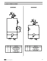
Page 22: ...BOILER TANK WATER SENSOR SAFETY THERMOSTAT MIXER MOTOR ADJUSTMENT THERMOSTAT HEATING ELEMENT 10 BASIC WIRING DIAGRAM 230 Volts Model ITEM DESCRIPTION P Ts M Tr R MAIN POWER SWITCH SAFETY THERMOSTAT MIXER MOTOR ADJUSTMENT THERMOSTAT HEATING ELEMENT P F N 0 I Rs S R Tr M Ts Ts P F N M Tr R 0 I 115 Volts Model ...

Reviews: