143
11. Service and Maintenance
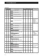
Error
codes
Appearance, Portion, Parts
seemed wrong
Method of check
Troubleshooting
Figure/
Table
Error
reset
A3
CT
disconnection
PCB (Main)
PCB (Main) should be replaced
Manual
A4
Protective
action against
excess
Current AC
current
detection
Unreasonable
operation
under/overload
Check the place of installation
(blockage of air inlet & outlet )
Check the excess gas
Ensure the installation position to
avoid blockage of air inlet & outlet
If excess gas is observed, collect all
refrigerant once, then recharge with
prescribed mass
Drop of power voltage Check the power voltage
(230V)
Confirm the power supply voltage
(230V)
Momentary stop of
power
(In case of lightning)
Restart operation
A5
Abnormal
revolution
of Compressor
Unreasonable
operation
under/overload
Check the place of installation
(blockage of air inlet & outlet )
Check the excess gas
Ensure the installation position to
avoid blockage of air inlet & outlet
If excess gas is observed, collect all
refrigerant once, then recharge with
prescribed mass
Drop of power voltage Check the power voltage
(230V)
Confirm the power supply voltage
(230V)
Fuse CF6
0639U : 250V 15A
1039U : 250V 25A
Check the electric continuity
Fuse CF6 by tester
If CF6 is blown, PCB (Main) should be
replaced
Fig. 3
Clogged the water
Pump and/or water
circuit
Check the Pump and water
circuit
Remove the blockage, then restart
operation
Drop of power voltage Check the power voltage
(230V) during operation
Confirm the power supply voltage
(230V)
Momentary stop of
power
(In case of lightning)
Restart operation
Compressor
or PCB (Main)
Other than described above
Compressor should be replaced
A6
Suction temp.
sensor error
Sensor, Temp. Suction Check the resistance by tester If the sensor is faulty, it should be
replaced
Table 3
Auto
A7
Defrost temp.
sensor error
Sensor, Temp. Defrost Check the resistance by tester If the sensor is faulty, it should be
replaced
Table 3
A8
Discharge
temp. sensor
error
Sensor, Temp.
Discharge
Check the resistance by tester
(*1)
If the sensor is faulty, it should be
replaced
Table 2
C1
Upper Fan
motor error
(1639U)
Fuse CF7
(250V T3.15A)
Check the electric continuity
Fuse CF7 by tester
If CF7 is blown, Fan motor and CF7
should be replaced
If CF7 is not blown, check the voltage
of Fan motor
If the voltage is normal, Fan motor
should be replaced
If the voltage is abnormal, PCB (Main)
should be replaced
Fig. 2
Manual
Fan motor (*2)
PCB (Main)
C2
Outdoor temp.
sensor error
Sensor, Temp. Outdoor Check the resistance by tester If the sensor is faulty, it should be
replaced
Table 1
Auto
(*1) In case of detecting open circuit of the discharge temperature sensor, error display appears 10 minutes after start operating.
In case of detecting short circuit of the discharge temperature sensor, error display appears immediately.
(*2) When checking fan motor and/or pump, turn OFF the power supply completely and check at their terminal or connector.
Summary of Contents for AEYC-0639U-CH
Page 156: ...20810030 M ...

