background image

24

3. Installation

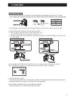
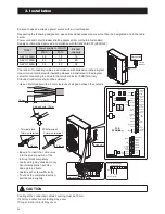
1. Isolate the mains power supply for the unit from the power source. 

Do not connect the Remote controller cord with the power on.

2. Remove the wiring lid.

3. Connect the Remote controller cord to the PCB(Terminal), No.1-2 (Remote Controller). It does not matter which 

wire of the Remote controller cord is connected to + and which to -. Take care not to let your screwdriver etc. 

touch any of the other electronic parts. Do not use a power driver.  It can damage the terminal screw holes.

4. If shielded wire is used, connect it to Terminal No.3(GND) on the PCB(Terminal).

5. Securely fasten the Remote controller cord with the cord fastening fitting. Leave the display board waterproofing 

cover removed.

  Master Remote controller

PCB(Terminal)

1 Remote controller

2 Remote controller

  Master Remote controller

Shielded cable

Shielded cable

Shielded cable

Remote

Controller

1

2

3

GND

PCB(Terminal)

Remote

Controller

1

2

3

GND

Slave Remote controller

  Master Remote controller

PCB(Terminal)

Remote

Controller

1

2

3

GND

Slave Remote controller

• The maximum length of the Remote controller cord is 100m. 

Use shielded wire in case of the length with 30m or longer.  

Connect the shielded wire to Terminal No.3(GND) on the PCB(Terminal).

2. Connecting with the equipment

Distance

Cable(mm

2

)

Shield

30m

MIN 0.5

non-shielded

30 100m

MIN 1.0

shielded

Summary of Contents for AEYC-0639U-CH

Page 1: ...MADE IN JAPAN AIR TO WATER HEAT PUMP HEATING AND COOLING MONOBLOC TYPE DC INVERTER INSTALLATION AND INSTRUCTION MANUAL KEEP THIS MANUAL FOR FUTURE REFERENCE GB AEYC 0639U CH AEYC 1039U CH AEYC 1639U CH ...

Page 2: ...eration Always ON 7 3 1 2 Sniffing operation Sniffing cycle 7 3 1 3 Unlock pump function 7 3 1 4 Pump output adjustment function 7 4 Frost protection 7 4 1 Frost protection based on Room air temperature 7 4 2 Frost protection based on Outdoor air temperature 7 4 3 Frost protection based on Outgoing water temperature 7 4 4 DHW tank frost protection 7 4 5 Secondary system circuit frost protection 7 ...

Page 3: ...nufacturing and packaging of the new equipment are ecological and or recyclable Directive 2002 96 EC WEEE Information for the users This product is in compliance with the EU 2002 96 EC Directive The symbol of the crossed bin on the appliance indicates that the product at the end of its life span must be treated separately from household waste It must be taken to a differentiated collection centre ...

Page 4: ...isk of death or serious injuries in the event of misuse Indicates the risk of personal injury or damage to property furniture or animals in the event of failure to follow the instructions Important information on safety is reported on the product and contained in this Manual Carefully read this installation manual before installing the unit Important information for correct installation is contain...

Page 5: ...isolating on the main switch of the electrical panel This unit must not be used by children or people with reduced physical sensory or mental capabilities or lack of experience and knowledge unless they are supervised Prohibition 1 2 MODE ON OFF TIMER ON OFF CAUTION Strict Enforcement Prohibition Prohibition Prohibition Prohibition Prohibition PROHIBITION 1 2 MODE ON OFF TIMER ON OFF CAUTION Stric...

Page 6: ... when draining the water STRICT ENFORCEMENT Prohibition Prohibition Prohibition Prohibition Prohibition Prohibition Hight temperature HIGH TEMPERATURE Do not try to repair or reconstruct by yourself Do not extend power supply cable or connect incorrectly GB Prohibition 1 2 MODE ON OFF TIMER ON OFF CAUTION Strict Enforcement Prohibition Prohibition Prohibition Prohibition Prohibition PROHIBITION CA...

Page 7: ...ift the unit by inserting hooks in the side handles but use specific equipment lifting devices trucks etc Do not rest liquid containers or other objects on the unit Do not use this unit for any purposes other than Heating and Cooling This appliance can be used by children aged from 8 years and above and persons with reduced physical sensory or mental capabilities or lack of experience and knowledg...

Page 8: ... Outdoor Temperature Heating C 20 to 43 Cooling C 18 to 43 20 to 43 15 to 43 Inlet Water Temperature C 18 to 55 Water Pressure MPa 0 1 to 0 3 Specifications are subject to change without notice Rating condition Heating Outdoor temperature DB WB 7 C 6 C Leaving water temperature 35 C Cooling Outdoor temperature 35 C Leaving water temperature 18 C Acoustic Noise Information The maximum sound pressur...

Page 9: ...equired This installation manual describes the correct connections using the installation set available from standard parts DANGER Installation work must be performed in accordance with national wiring standards by authorized personnel only For the air to water heat pump to operate satisfactorily install it as outlined in this installation manual Also do not use an extension cord Do not turn on th...

Page 10: ...on mounts and fix the unit securely Over 300 mm Over 600 mm Over 100 mm Over 100 mm Over 600 mm AEYC 1039U CH 882 850 24 R1 25A R1 25A 25 330 38 480 173 155 540 155 7570 357 Circulating water return port Circulating water outgoing port AEYC 1039U CH Over 300 mm Over 600 mm Over 100 mm Over 100 mm Over 600 mm AEYC 1639U CH 680 185 357 80 80 24 1000 36 37 330 1418 205 590 205 Circulating water outgo...

Page 11: ... which can withstand the weight of the unit and vibration Please make sure it is installed level 2 Provide the indicated space to ensure good airflow 3 Do not install the unit near a source of heat steam or flammable gas 4 During heating operation condensate water flows from the unit Therefore install the unit in a place where the condensate water flow will not be obstructed 5 Do not install the u...

Page 12: ...ator Pump1 for quick installation with the aid of a few external components 3 3 Main components Wiring lid Screw AEYC 0639U CH AEYC 1039U CH AEYC 1639U CH PCB Terminal Airpurge valve Terminal block Pump Compressor Pressure relief valve PCB Main Wiring lid Screw PCB Terminal Airpurge valve Terminal block Pump Compressor Pressure relief valve PCB Main Wiring lid Screw PCB Main PCB Terminal Terminal ...

Page 13: ... Medium ON 4 3 2 1 6 5 8 7 OFF Level 1 Minimum CAUTION The quantity should not be less than 15L min 0 2 4 6 8 10 12 14 m 0 10 20 30 40 Level3 Level2 Level1 50 L min AEYC 1639U 0 2 4 6 8 10 12 14 m 0 10 20 30 40 Level3 Level2 Level1 50 L min 0 1 2 3 4 5 6 7 8 m 0 10 5 20 15 25 30 35 40 L min Level3 Level2 Level1 CAUTION The quantity should not be less than 10L min AEYC 1039U 0 1 2 3 4 5 6 7 8 9 10 ...

Page 14: ...er tank Mani fold Outlet Inlet DHW tank M Space Heating Dehumidifier M Fan convector Radiant panel F P T P T 1 2 1 2 3 8 9 8 9 6 5 7 4 11 13 14 12 10 15 19 17 18 16 16 19 20 Shut off valve Vibration damper joint Air bleed valve Fill drain valve Water line filter Flow switch Expansion vessel Pressure gauge Thermometer Backup heater DHW 3way valve DHW tank temperature probe DHW Electric heater EHS B...

Page 15: ...eater Therefore protect the exchanger using a removable mesh filter The gauge of the filter net must be of at least 10 meshes cm2 7 After system assembly flush and clean the whole system paying particular attention to the state of the filter 8 In cases where water must be cooled at temperatures below 5 C of if the device is installed in areas subject to temperatures below 0 C it is essential to mi...

Page 16: ...ealant must be able to withstand the pressures and temperatures of the system When using non brass metallic piping make sure to insulate both materials from each other to prevent galvanic corrosion Because brass is a soft material use appropriate tooling for connecting the water circuit Inappropriate tooling will cause damage to the pipes The unit is the only to be used in a closed water system Ap...

Page 17: ... PCB Terminal is pressed the water pump comes into operation to circulate water Each digital segment on the right side of the PCB Terminal lights up sequentially during pump operation The pump is stopped automatically after 10 minutes of operation If air could not be released this way from the water circuit then press Pump SW again after the pump has stopped If you want to stop the pump before it ...

Page 18: ...r appliance Check that the voltage and frequency of the electric system are those required Ensure the impedance of the power supply line conforms to the electrical absorption of the unit specified on its data plate It is necessary to incorporate a main switch in the fixed wiring or other means for disconnection having a contact separation in all poles in accordance with relevant local and national...

Page 19: ...ce with the related laws and regulations and electric company standards The circuit breaker is installed in the permanent wiring Always use a circuit that can trip all the poles of the wiring and has an isolation distance of at least 3 mm between the contacts of each pole CAUTION The power source capacity must be the sum of the air to water heat pump current and the current of other electrical app...

Page 20: ... way valve 8 9 10 11 12 13 14 Dual Set Point Control Heating Cooling mode Flow switch Night mode Low tariff RS485 GND 45 46 47 48 49 50 31 32 24 25 26 27 28 29 30 15 16 N 41 42 43 44 51 52 Electric heater 10 mm 30 mm Crimp on terminal Stripped wire 10mm Sleeve Terminal block Crimp on terminal Sleeve PCB Terminal Circuit breaker Distribution board Be sure to use an exclusive power source with a cir...

Page 21: ...hase of the power supply matches with the phase of the terminal board If the phases do not match the compressor will rotate in reverse and will not be able to compress Tightening torque M4 screw 1 2 to 1 8 N m 12 to 18 kgf cm M5 screw 2 0 to 3 0 N m 20 to 30 kgf cm WARNING Before starting work check that power is not being supplied to the controller and outdoor unit Match the terminal board number...

Page 22: ...e controller installation Do not install the Remote controller in moist conditions such as in the bathroom The Remote controller is not waterproof Keep the distance of 1cm or more between the surrounding wall and another Remote controller in order for the cover of the Remote controller to touch any obstacles when it is open fully Never install above a gas stove or burner or any other combustion de...

Page 23: ...ed Do not damage the PCB of Remote controller with too much pressure when the terminal is installed Never use electric screwdriver It can damage the screw hole which cause contact failure When the wiring is exposed Fix the mounting plate to the solid position of the wall with the attached tapping screws L35 2 screws If you tighten the screws too strongly this can deform or break the screw hole of ...

Page 24: ...Terminal 5 Securely fasten the Remote controller cord with the cord fastening fitting Leave the display board waterproofing cover removed Master Remote controller PCB Terminal 1 Remote controller 2 Remote controller Master Remote controller Shielded cable Shielded cable Shielded cable Remote Controller 1 2 3 GND PCB Terminal Remote Controller 1 2 3 GND Slave Remote controller Master Remote control...

Page 25: ...nected Note2 Slave Remote controller functions can be used when Master Remote controller is not connected However parameter setting ON OFF of DHW or time setting and so on cannot be set and changed by Slave Remote controller Remote Controller Back side DIP SW SW1 OFF Master for Zone1 1 2 ON SW1 ON Slave for Zone2 1 2 ON 2 Remote controllers can be connected by 1 Master Remote controller for Zone1 ...

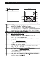
Page 26: ...or parameter setting select and change the digit to be entered Push the Menu button together for 3 seconds to set the parameters installer level During alarm display push and button of Master Remote controller together for 3 seconds to reset alarm display 7 Set confirm Push the Set button During the programming to save the setting Change display Clock Humidity value Room set temperature Humidity v...

Page 27: ...of DHW EHS or Backup heater active Dehumidifier is active Outdoor fan is active System pump is active Compressor active Flashing compressor delay DHW production of Comfort mode is enabled Flashing In DHW mode DHW production is stopped for Heating Cooling DHW production of Economy mode is enabled Time bands for DHW is enabled Displayed together with DHW Comfort or Economy icon DHW force mode is ena...

Page 28: ...tion is stopped Note In recovering from blackout the HP unit will operate as below depending on the condition before the blackout The last operating condition before the blackout If ON OFF switch is OFF the unit will recover from the blackout in OFF state If ON OFF switch is ON the unit will recover from the blackout in the last operating mode before the blackout However the time band operation is...

Page 29: ...ay of the week changes blinking to lighted 3 When the day of the week is set 12 00 blinks set the current time by pressing the or button When the or button is pressed the time changes in 1 minute increments when the or button is pressed and held it changes in 10 minute increments 2 3 1 2 3 5 2 Setting the day and time When the Set button is pressed to save the setting then it reverts to normal ope...

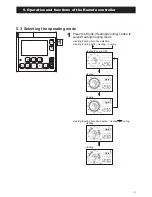
Page 30: ...on and before setting the time or when the unit is reset after a power failure or after the power had been turned OFF for an extended period of time if the time has not been set 12 00 and Mon blink indicating that the time has not yet been set The time band operation Heating Cooling DHW can be carried out only once the current time has been set Heating Cooling by Mode button DHW production by DHW ...

Page 31: ...ling mode 1 Heating Cooling OFF Heating Cooling Heating Cooling Heating Cooling time band active Heating Cooling Heating Cooling time band disable Heating Cooling OFF Heating Cooling 5 3 Selecting the operating mode 5 Operation and functions of the Remote controller ...

Page 32: ...d in Heating Cooling Note 1 During time band operation the room setting temperature displayed on Remote controller is the setting temperature of current operation in Comfort or Economy 2 Even during time band operation room setting temperature can be changed by Up or Down button of the Remote controller However when the time band of Comfort Economy is switched the setting Room air temperature will...

Page 33: ...and Economy 40 C DHW button Economy 40 C Time band Comfort 50 C Low tariff 50 C DHW button Force 60 C Time band Economy 40 C Comfort 50 C Low tariff 50 C 5 4 Domestic Hot Water production Force 1 2 3 seconds 2 Press the DHW button for 3 seconds to enable DHW Force mode In Force mode hot water will be supplied to DHW tank until the DHW tank temperature reaches the Over boost set point Force mode wi...

Page 34: ...e bands 1 Push the Timer for Heating Cooling button once to activate the time bands once again to deactivate If the time bands is enabled On icon is displayed If the time band is not set at the plant shipment the time band cannot be switched ON by the button 34 5 Operation and functions of the Remote controller ...

Page 35: ...of the week using the or button and then press the Set button to save the setting The time bands can be programmed by selecting the days in present group or for each individual day Note Press the Return button to return to the previous item Press the Timer for Heating Cooling button for 3 seconds again to return to normal operation or simply do nothing for approximately 2 minutes Day setting Mon T...

Page 36: ... Set button to save the setting Note The day of the week setting is prioritized as follows Day of the week Weekday Weekend 7 days Example When 7 days and Wednesday are set to ON Monday Tuesday Thursday Friday Saturday and Sunday are common settings while Wednesday is a single setting ON OFF setting 4 4 36 5 Operation and functions of the Remote controller ...

Page 37: ...k set the 1st ON time When the or button is pressed the time changes in 15 minute increments Press the Set button to save the setting 1st ON time setting Comfort set point setting Economy set point setting Then the Economy icon displays and set point temperature Default 18 0 C blinks And change the Economy set point temperature by using the or button and press the Set button to save the setting Th...

Page 38: ...in steps 6 to 8 9 When the settings prior to the 3rd time band OFF time have been specified the relevant day of the week setting is complete and it returns to step 2 Then set other zones and other day of the week Note1 When there is no setting for the 2nd and 3rd time bands press Set button to proceed to 3rd OFF time The same time will be applied for the 2nd and 3rd time bands When the OFF time is...

Page 39: ...min Max Unit U 01 16 H eating Cooling time bands setting Zone1 0 disable 1 active Comfort or Economy 0 0 1 U 01 17 H eating Cooling time bands setting Zone2 0 disable 1 active Comfort or Economy 0 0 1 U 01 18 D HW time band setting 0 disable 1 enable 0 0 1 I 11 00 T ime band is ON OFF on Monday 0 OFF 1 ON 0 0 1 I 11 01 Comfort room set temperature on Monday 20 0 12 0 40 0 0 5 C I 11 02 Economy roo...

Page 40: ...the setting mode 1 1 2 5 6 Setting the time bands for DHW Low tariff and Night mode 3 seconds Note Press the Return button to return to the previous item Press the Timer for DHW button for 3 seconds again to return to normal operation or simply do nothing for approximately 2 minutes 2 Select the mode DHW Select the mode Low tariff Select the mode Night 40 5 Operation and functions of the Remote co...

Page 41: ...and DHW Economy set point Default 40 C blinks change the DHW Economy set point using the or button and press Set button to save the setting The temperature can be specified in increments of 0 5 C For the Low tariff and Night mode settings there are no temperature settings then proceed to the next item DHW Comfort set point setting DHW Economy set point setting 3 3 5 Operation and functions of the ...

Page 42: ...been saved 1 On changes to 1 Off Set the 1st time band OFF time After entering the Off time the gauge of the circle graph for ON time will be lit and then press the Set button to save the setting 6 When the 1st OFF time has been saved 1 Off changes to 2 On Set the ON and OFF times of the 2nd and 3rd time bands according to the same procedures as in steps 4 to 6 4 5 4 5 6 1st ON time setting 1st OF...

Page 43: ...t to OFF at 24 00 on that day and then set it to ON at 0 00 in the next day The Time bands can be set using the Master Remote controller The Slave Remote controller cannot be used for this setting 7 When the setting of the 3rd time band OFF time has been specified the relevant mode setting is complete Return to step 2 for mode selection 8 Specify the setting for each mode according to the same pro...

Page 44: ...4 00 15min I 13 11 Low tariff 1st ON time 0 00 0 00 24 00 15min I 13 12 Low tariff 1st OFF time 0 00 0 00 24 00 15min I 13 13 Low tariff 2nd ON time 0 00 0 00 24 00 15min I 13 14 Low tariff 2nd OFF time 0 00 0 00 24 00 15min I 13 15 Low tariff 3rd ON time 0 00 0 00 24 00 15min I 13 16 Low tariff 3rd OFF time 0 00 0 00 24 00 15min I 13 21 Night mode 1st ON time 0 00 0 00 24 00 15min I 13 22 Night m...

Page 45: ...layed in the display Among 4 digits of parameter numbers 2 digits of them which indicates group or code numbers will be flashed Press or button to switch the flashing 2 digits from left 2 showing group numbers to right 2 showing code numbers 3 seconds Note1 The Parameter setting menu can be set using the Master Remote controller The Slave Remote controller cannot be used for this 5 Operation and f...

Page 46: ...umber Display parameter value Change parameter value Saved parameter value If invalid parameters the value which is not on the parameter list or not accessible due to INSTALLER level are entered and Set button is pressed the indication is displayed Press the Return button to return to the previous item 3 46 5 Operation and functions of the Remote controller ...

Page 47: ...geable items read only items the number displayed remains on then pressing the Set button does not affect the display 5 Press the Return or Set button the parameter code numbers blinks To access other parameter code numbers without an interval repeat the same steps 6 To return to normal operation press and hold the Menu button for 3 seconds or simply do nothing for approximately 10 minutes 5 6 Ret...

Page 48: ... of setting parameters are same as USER level 4 To return to normal operation press and hold the Menu and button for 3 seconds or simply do nothing for approximately 10 minutes 2 2 If invalid parameters the value which is not on the parameter list or not accessible level are entered and Set button is pressed the indication is displayed Press the Return button to return to the previous item Note1 T...

Page 49: ... BUFFER T probe Mix water T probe 3 way mixing valve RS485 Dehumidifier Alarm Pump1 Pump2 Neutral N C Neutral EHS Heating Cooling mode output Phase Signal 3 way valve 8 9 10 11 12 13 14 Dual Set Point Control Heating Cooling mode Flow switch Night mode Low tariff RS485 GND 45 46 47 48 49 50 31 32 24 25 26 27 28 29 30 15 16 N 41 42 43 44 51 52 Electric heater Reset SW Pump SW 49 6 Electrical connec...

Page 50: ...ltage free contact 12V10mA 20 21 C onfigurable input ON OFF remote contact EHS Alarm 22 23 Dual Set Point Control 24 25 Heating Cooling mode remote contact 26 27 Flow switch 28 29 Night mode 30 31 Low tariff Analogue Digital OUTPUTS Terminal Function Analogue Input Digital Input 4 5 6 3way mixing valve 6 0 10V DC control 4 5 24V AC N Neutral 1ph 230V 1A Neutral 41 42 EHS External heat source for s...

Page 51: ...ontroller only 1 enable 0 0 1 I 51 20 Terminal 20 21 ON OFF remote contact or EHS A larm input 0 disable 1 ON OFF remote contact 2 EHS Alarm input 0 0 2 ON OFF by R emote controller 0 enable 1 ON disable OFF enable 2 enable I 51 22 T erminal 22 23 Dual set point control 0 disable 1 enable 1 0 1 I 51 24 Terminal 24 25 Heating Cooling mode remote contact 0 disable Remote controller only 1 Cooling is...

Page 52: ...eater 0 DHW Electric heater 1 Backup heater 0 0 1 I 51 47 T erminal 47 Alarm Configurable output 0 disable 1 Alarm 2 Ambient temperature reached 0 0 2 I 51 48 T erminal 48 Pump1 0 disable 1 1st Additional water pump1 for Zone1 0 0 1 I 51 49 T erminal 49 Pump2 0 disable 1 2nd Additional water pump2 for Zone2 0 0 1 I 51 50 T erminal 50 51 52 DHW 3way valve 0 disable 1 enable 1 1 1 52 6 Electrical co...

Page 53: ...d parameter the operating mode cannot be changed on the Remote controller Parameters Level Parameter Function description Display Input value Remarks Group Code Default min Max Unit I 51 24 T erminal 24 25 Heating Cooling mode remote contact 0 disable Remote controller only 1 Cooling is CLOSE contact Heating is OPEN contact 2 Cooling is OPEN contact Heating is CLOSE contact 0 0 2 Heating Cooling m...

Page 54: ...e 1 enable Outgoing water set point 0 Fixed set point 1 Climatic curve enabled 0 0 1 I 21 21 Cooling Zone 1 Fixed Outgoing water set point in Cooling 7 0 7 0 23 0 0 5 C I 21 30 C ooling Zone2 enable Outgoing water set point 0 Fixed set point 1 Climatic curve enabled 0 0 1 I 21 31 Cooling Zone2 Fixed Outgoing water set point in Cooling 7 0 7 0 23 0 0 5 C I 21 41 Hysteresis of water set point in Hea...

Page 55: ...0 0 1 I 21 02 Max Outgoing water temperature in Heating mode Tm1 Zone1 45 0 23 0 60 0 0 5 C I 21 03 Min Outgoing water temperature in Heating mode Tm2 Zone1 30 0 23 0 60 0 0 5 C I 21 04 Min Outdoor air temperature corresponding to max Outgoing water temperature Te1 Zone1 0 0 20 0 50 0 0 5 C I 21 05 Max Outdoor air temperature corresponding to max Outgoing water temperature Te2 Zone1 20 0 0 0 40 0 ...

Page 56: ...e Tm2 Zone1 18 0 7 0 23 0 0 5 C I 21 24 Min Outdoor air temperature corresponding to max Outgoing water temperature Te1 Zone1 25 0 0 0 50 0 0 5 C I 21 25 Max Outdoor air temperature corresponding to max Outgoing water temperature Te2 Zone1 35 0 0 0 50 0 0 5 C I 21 30 C ooling Zone2 enable outgoing water set point 0 Fixed set point 1 Climatic curve enabled 0 0 1 I 21 32 Max Outgoing water temperatu...

Page 57: ...door air temperature probe and Par5109 1 enable the detected temperature is applicable to the followings 7 2 2 Climatic curve 8 2 3 Heat pump DHW heater 8 3 1 2 Depends on Outdoor air temperature 8 3 2 Backup heater in supplementary mode 8 4 1 EHS in Replacement mode 8 4 2 EHS in Supplementary mode Additional probe Outdoor air temperature PCB Terminal OUTDOOR T probe 9 10 On board probe Outdoor ai...

Page 58: ...be set higher in Heating or lower in Cooling than set points of Zone1 and Zone2 Buffer tank temperature probe PCB Terminal Buffer tank BUFFER T probe 11 12 Parameters Level Parameter Function description Display Input value Remarks Group Code Default min Max Unit I 51 11 T erminal 11 12 Buffer tank temperature probe 0 disable 1 enable 0 0 1 To be set to the following combinations Par5111 0 Par4200...

Page 59: ...r4200 5148 5149 Parameters Level Parameter Function description Display Input value Remarks Group Code Default min Max Unit I 41 00 T he HP unit turns ON OFF based on 0 Room set point 1 Water set point 1 0 1 I 42 00 T ype of configuration of Main water pump 0 always ON 1 ON OFF based on Buffer tank temperature 2 ON OFF based on Sniffing cycles 0 0 2 I 51 07 T erminal 7 8 DHW tank temperature probe...

Page 60: ...r temp 60 5 C Cooling Outgoing water temp Water set point Par2120 2135 1 C Outgoing water temp 5 0 C When the Outgoing water temperature reaches the set point and after the compressor is turned OFF or when the conditions below are met the compressor shall be turned ON However the compressor is not turned ON during 3 minutes OFF ON waiting time When the Room air temperature sensor built in the Remo...

Page 61: ...ature is in the following conditions or the Outgoing water temperature reaches the set point to protect HP unit Heating Buffer tank temp Buffer tank set point Par2161 Outgoing water temp Maximum Outgoing water set point 60 C 1 C Outgoing water temp 62 5 C Cooling Buffer tank temp Buffer tank set point Par2162 Outgoing water temp Minimum Outgoing water set point 7 C 1 C Outgoing water temp 5 0 C Wh...

Page 62: ...re has reached the Room air set point the external water pump in the applicable Zone shall be turned OFF Heating Room air temp Room air set point Par0111 0112 1101 1102 1111 1112 1291 1292 Cooling Room air temp Room air set point Par0111 0112 1101 1111 1112 1291 1292 After the compressor has been turned OFF when the Room air temperature reaches the Room air set point the compressor will be turned ...

Page 63: ...temp 62 5 C When the DHW tank temperature reaches the water set point or when the conditions below are met after the compressor is turned OFF due to the set point to protect HP unit the compressor is turned ON However the compressor is not turned ON during 3 minutes OFF ON waiting time Comfort DHW tank temp DHW Comfort set point Par3111 Hysteresis Par3113 Economy DHW tank temp DHW Economy set poin...

Page 64: ... 1 set temp 1 set temp 1 set temp 1 Water set temp C Water set temp C set temp Hysteresis set temp Hysteresis Heating ON Cooling ON Water temperature is stable Water temperature is stable minimum minimum ON ON OFF OFF OFF OFF Comp OFF ON Comp OFF ON set point 1 C 3min Comp OFF set point 1 C 3min Comp OFF 64 7 Unit Management ...

Page 65: ...ions described in paragraph on 7 4 Frost protection In order to minimise energy consumption the Main water pump can be configured to start only when there is demand from the temperature controller The pump will be activated periodically for a time set by parameter Five seconds before the cycle ends if the Outgoing water temperature is lower than water set point hysteresis in Heating mode or higher...

Page 66: ...11 T erminal 11 12 Buffer tank temperature probe 0 disable 1 enable 0 0 1 7 3 1 3 Unlock pump function When the HP unit is stopped for more than 48 hours the Main water pump turns ON for few seconds to prevent locking up and increases the life time of the pump In the case of the main pump pump1 pump2 the down time after the previous operation stop is counted individually Furthermore the pump opera...

Page 67: ...HP unit At the factory shipment both SW5 and SW6 are OFF which means Level 3 If both are ON it is Level 3 CAUTION The quantity should not be less than 15L min 0 2 4 6 8 10 12 14 m 0 10 20 30 40 Level3 Level2 Level1 50 L min AEYC 1639U 0 2 4 6 8 10 12 14 m 0 10 20 30 40 Level3 Level2 Level1 50 L min 0 1 2 3 4 5 6 7 8 m 0 10 5 20 15 25 30 35 40 L min Level3 Level2 Level1 CAUTION The quantity should ...

Page 68: ...nit will operate based on the Frost protection set point if this shuts down high pressure switch activation shut down due to heat exchanger Outgoing water temperature etc the other available heat sources will be activated Note2 Additional water pumps 1 and 2 are tuned ON together with the main pump Parameters Level Parameter Function description Display Input value Remarks Group Code Default min M...

Page 69: ... the Outgoing water temperature reaches the 7 C hysteresis 3 C Parameters Level Parameter Function description Display Input value Remarks Group Code Default min Max Unit I 43 11 Start temperature of Frost protection on Outdoor air temperature 4 0 0 0 10 0 0 5 C I 43 12 Hysteresis of Outdoor air temperature 3 0 0 5 5 0 0 5 C I 43 13 Backup heater set point during Frost protection 4 0 0 0 10 0 0 5 ...

Page 70: ...e Outgoing water temperature reaches Parameters Level Parameter Function description Display Input value Remarks Group Code Default min Max Unit I 43 21 Start temperature of Frost protection on Outgoing water temperature 4 0 0 0 10 0 0 5 C I 43 22 Hysteresis of Outgoing water temperature 3 0 0 5 5 0 0 5 C I 43 13 Backup heater set point during Frost protection 4 0 0 0 10 0 0 5 C I 43 14 Hysteresis...

Page 71: ...onal pumps will be activated according to the setting of Par4220 Note1 The function is active even when the unit is switched OFF Note2 DHW tank frost protection is available only if there is an electric element in DHW tank Parameters Level Parameter Function description Display Input value Remarks Group Code Default min Max Unit I 43 31 Start temperature of Frost protection of DHW tank temperature...

Page 72: ...in Max Unit I 31 01 D HW production priority setting 0 DHW is unavailable 1 DHW is available and priority DHW over space Heating 2 DHW is available and priority space Heating over DHW 0 0 2 I 51 20 Terminal 20 21 ON OFF remote contact or EHS Alarm input 0 disable Remote controller only 1 ON OFF remote contact 2 EHS Alarm input 0 0 2 ON OFF by Remote controller 0 enable 1 ON disable OFF enable 2 en...

Page 73: ...OFF remote contact first If the Remote controller is connected turn ON both Remote controller by ON OFF button and ON OFF remote contact then turn ON HP unit Parameters Level Parameter Function description Display Input value Remarks Group Code Default min Max Unit I 31 01 D HW production priority setting 0 DHW is unavailable 1 DHW is available and priority DHW over space Heating 2 DHW is availabl...

Page 74: ...rn ON Comfort Force turn OFF OFF Comfort no activated turn ON Comfort turn OFF OFF Economy no activated turn ON Comfort Economy turn OFF OFF no activated Comfort turn ON Comfort turn OFF no activated Economy turn ON Economy turn OFF no activated no activated turn ON Comfort turn OFF OFF During Force or Economy mode by the Remote controller button if Par5119 is changed from 0 to 1 and then DHW remo...

Page 75: ...ven when the unit is switched OFF from the remote contact ON OFF remote contact Contact OPEN HP unit OFF Contact CLOSE HP unit ON 20 21 PCB Terminal ON OFF or EHSAlarm Parameters HP unit states by ON OFF of Remote controller and remote contact Level Parameter Function description Display Input value Remarks Group Code Default min Max Unit I 51 20 Terminal 20 21 ON OFF remote contact or EHS Alarm i...

Page 76: ...oller if the ON OFF remote contact ON and Heating or Cooling is in operation and if the Mode button of Remote controller is used to select OFF among Heating Cooling OFF the ON OFF remote contact ON condition will be top priority than the Mode button of Remote controller Heating ON OFF contact ON OFF ON OFF ON OFF DHW contact HP unit HP unit states Heating DHW DHW DHW has priority than Heating Cool...

Page 77: ...he compressor will stop In order to heat the water also if the external heat source doesn t work because it is faulty EHS Alarm remote contact Contact OPEN EHS Normal Contact CLOSE EHS Alarm EHS Stopped 20 21 PCB Terminal ON OFF or EHSAlarm Parameters Level Parameter Function description Display Input value Remarks Group Code Default min Max Unit I 51 20 Terminal 20 21 ON OFF remote contact or EHS...

Page 78: ...p the compressor will not be turned ON unless the flow switch is CLOSED water flow detected After starting operation once the flow switch is OPEN no water flow In case of Flow switch error for 2min or the system carries out 5 retries within 60min then an alarm will appear and the compressor will be turned OFF From the first error to the fourth error the compressor will be stopped temporarily and r...

Page 79: ...oint control Input contact Set point for Zone2 is Contact OPEN Set point 1 Contact CLOSE Set point 2 22 23 PCB Terminal Dual Set Point Control Parameters Level Parameter Function description Display Input value Remarks Group Code Default min Max Unit I 51 22 T erminal 22 23 Dual set point control 0 disable 1 enable 1 0 1 The temperature of the requested water from the HP unit is calculated through...

Page 80: ...e Remarks Group Code Default min Max Unit I 51 48 T erminal 48 Pump1 0 disable 1 1st Additional water pump1 for Zone1 0 0 1 I 51 49 T erminal 49 Pump2 0 disable 1 1st Additional water pump1 for Zone1 0 0 1 Additional water pump1 230V 50Hz P PCB Terminal Dehumidifier Neutral EHS 45 46 47 48 49 N 41 42 43 44 Electric heater Heating Cooling mode output Alarm Pump1 Pump2 Parameters Level Parameter Fun...

Page 81: ...on Main water pump setting Depending on Main water pump setting but always OFF when the DHW mode is activated Always ON apart from if any alarms are active or if the HP unit is in OFF mode ON OFF based on Room air temperature set by Remote controller HP unit 3way valve DHW tank M Pump 1 Space Heating Buffer tank 3way valve DHW tank M Pump 1 Space Heating HP unit 81 7 Unit Management ...

Page 82: ...DHW Additional water pump2 230V 50Hz P PCB Terminal Dehumidifier Neutral EHS 45 46 47 48 49 N 41 42 43 44 Electric heater Heating Cooling mode output Alarm Pump1 Pump2 Parameters Level Parameter Function description Display Input value Remarks Group Code Default min Max Unit I 51 49 T erminal 49 Pump2 0 disable 1 2nd Additional water pump2 for Zone2 0 0 1 I 42 20 T ype of operation of additional w...

Page 83: ...p setting Depending on Main water pump setting but always OFF when the DHW mode is activated Always ON apart from if any alarms are active or if the HP unit is in OFF mode ON OFF based on Room air temperature set by Remote controller 3way valve DHW tank M Pump1 Space Heating Pump2 Space Heating HP unit HP unit Buffer tank 3way valve DHW tank M Pump1 Space Heating Fan coil M Pump2 83 7 Unit Managem...

Page 84: ...g mode the floor heating loop should be closed via the 3way valve so that cold water does not run into the floor heating loop This output allows control of the 3way valve PCB Terminal 43 44 Heating Cooling mode output Heating Cooling is Contact OPEN Not active Contact CLOSE Active 230V 50Hz Parameters Level Parameter Function description Display Input value Remarks Group Code Default min Max Unit ...

Page 85: ...utput occurs at the Alarm contact Parameters Level Parameter Function description Display Input value Remarks Group Code Default min Max Unit I 51 47 T erminal 47 Alarm Configurable output 0 disable 1 Alarm 2 Ambient temperature reached 0 0 2 Visual or audible signal device PCB Terminal Dehumidifier Neutral EHS 45 46 47 48 49 N 41 42 43 44 Electric heater Heating Cooling mode output Alarm Pump1 Pu...

Page 86: ...l47 will be closed Fan coil unit PCB Terminal Dehumidifier Neutral EHS 45 46 47 48 49 N 41 42 43 44 Electric heater Heating Cooling mode output Alarm Pump1 Pump2 Parameters Level Parameter Function description Display Input value Remarks Group Code Default min Max Unit I 04 00 Which Remote controller will measure the Room air temperature to stop Fan coil system 0 Master Remote controller 1 Slave R...

Page 87: ...lue If Par5128 is changed to 1 enable then Par5130 will be also changed to 1 enable Note2 During Night mode with Night mode contact ON if Par5128 is changed to 0 the HP unit will continue to operate in Night mode During Night mode by the Remote controller button if Par5128 is changed to 1 the HP unit will follow the signal of ON OFF by Night mode contact Parameters Level Parameter Function descrip...

Page 88: ... relevant parameter Note1 Par5128 Night mode and Par5130 Low tariff are automatically synchronized to same value If Par5128 is changed to 1 enable then Par5130 will be also changed to 1 enable Note2 During Low tariff with Low tariff contact ON if Par5130 is changed to 0 the HP unit will continue to operate in Low tariff During Low tariff by the Remote controller button if Par5128 is changed to 1 t...

Page 89: ...ensor A demand for dehumidification occurs only in Cooling mode Parameters Level Parameter Function description Display Input value Remarks Group Code Default min Max Unit I 51 17 T erminal 17 18 Humidity sensor 0 disable 1 enable 0 0 1 I 51 45 T erminal 45 Dehumidifier 0 disable 1 enable 0 0 1 PCB Terminal 230V 50Hz Dehumidifier Neutral EHS 45 46 47 48 49 N 41 42 43 44 Electric heater Heating Coo...

Page 90: ... room humidity detected with humidity sensor with the humidity set point Par 4401 4402 and switches the external dehumidifier connected to the Terminal 45 N Parameters Level Parameter Function description Display Input value Remarks Group Code Default min Max Unit I 44 01 Room relative humidity value 60 0 100 1 I 44 02 Hysteresis value 10 1 100 1 I 44 03 Humidity sensor property Voltage value1 0 0...

Page 91: ...ed directly to the system without Buffer tank the maximum Room humidity compensation has effect on the Outgoing water temperature from the HP unit If the HP unit is connected to the Buffer tank and the low temperature Zone with a 3way mixing valve is enabled the maximum Room humidity compensation has effect on the Outgoing water temperature from mixing valve Parameters Level Parameter Function des...

Page 92: ...the Slave Remote controller it is possible to turn the HP unit ON OFF and set the Room air temperature The time and date setting and time band setting are carried out using the Master Remote controller DHW tank The DHW tank loading loop cylinder coil The Master Remote controller is used to specify the DHW related settings Each Zone can generate a demand to the HP unit and or EHS as Electric heater...

Page 93: ...ed as below and the HP unit control in main system is as below 1 to 4 S1 Sensor Outgoing water temperature on HP unit S2 Sensor DHW tank temperature S3 Sensor Buffer tank temperature S4 Sensor Mixed water temperature T1 Sensor Room air temperature Zone1 on Master Remote controller T2 Sensor Room air temperature Zone2 on Slave Remote controller 1 Zone1 only In the case of water temp control Par4100...

Page 94: ...t is OPEN it will be set point of Zone1 If Terminal 22 23 Dual set point is CLOSED it will be set point of Zone2 If dual set point is enable Terminal 22 23 is CLOSED and both set points of Zone1 and 2 are not reached the target set point will be the higher set point compared to the set point of Zone1 and Zone2 Parameters Level Parameter Function description Display Input value Remarks Group Code D...

Page 95: ...e turned ON OFF by T1 and the set point of Remote controller DH W tank The HP unit operates with maximum water temperature in Heating 60 C in order for S2 to reach the DHW set point Parameters Level Parameter Function description Display Input value Remarks Group Code Default min Max Unit I 41 00 T he HP unit turns ON OFF based on 0 Room set point 1 Water set point 1 0 1 S1 S2 M HP unit DHW tank T...

Page 96: ...g mode shall be higher than water set points of Zone1 and Zone2 In Cooling mode on the other hand Buffer tank set point shall be lower than water set points of Zone1 and Zone2 Pump1 shall be turned ON OFF by T1 of Zone1 and Room set point of the Master Remote controller and Pump2 shall be turned ON OFF by T2 of Zone2 and Room set point of the Slave Remote controller Mixing valve is controlled in o...

Page 97: ...k M Space Heating HP unit DHW tank temperature probe DHW tank temperature probe PCB Terminal DHW T probe 7 8 DHW 3way valve M Neutral N C Phase Signal 3 way valve 50 44 51 52 mode output Parameters Level Parameter Function description Display Input value Remarks Group Code Default min Max Unit I 51 07 T erminal 7 8 DHW tank temperature probe 0 disable 1 enable 0 0 1 I 51 50 T erminal 50 51 52 DHW ...

Page 98: ...e The DHW 3way valve will change over according to the function described in the following graph from system to DHW and vice versa Minimum compressor OFF ON time 3min is a fixed value The interval time is necessary for refrigerant cycle safety it cannot be changed Note If the Defrost cycle is required during DHW production the 3way valve will change over to the system to avoid Cooling the DHW tank...

Page 99: ...tton Timer for DHW button DHW remote contact Contact OPEN DHW OFF Contact CLOSE DHW ON 18 19 PCB Terminal COM DHWRemote Contact Parameters Level Parameter Function description Display Input value Remarks Group Code Default min Max Unit I 31 01 D HW production priority setting 0 DHW is unavailable 1 DHW is available and priority DHW over space Heating 2 DHW is available and priority space Heating o...

Page 100: ...nit only Par3102 2 Fill DHW tank with DHW Electric heater only Parameters Parameters Level Parameter Function description Display Input value Remarks Group Code Default min Max Unit I 31 11 DHW Comfort set temperature 50 0 40 0 60 0 0 5 C I 31 12 DHW Economy set temperature 40 0 30 0 50 0 0 5 C I 31 13 DHW set point hysteresis 3 0 0 5 10 0 0 5 C I 31 14 DHW Over boost mode set point 60 0 50 0 90 0...

Page 101: ...ameter Function description Display Input value Remarks Group Code Default min Max Unit I 31 02 T ype of configuration to heat the DHW 0 Heat pump Heater 1 Heat pump only 2 Heater only 1 0 2 I 31 11 DHW Comfort set temperature 50 0 40 0 60 0 0 5 C I 31 12 DHW Economy set temperature 40 0 30 0 50 0 0 5 C I 31 13 DHW set point hysteresis 3 0 0 5 10 0 0 5 C I 31 14 DHW Over boost set point 60 0 50 0 ...

Page 102: ...oling The unit will be available for space Heating Cooling for a minimum time set using Par3122 15min even if there is no demand from the system Parameters Level Parameter Function description Display Input value Remarks Group Code Default min Max Unit I 31 21 Max time for DHW request 60 0 900 1min I 31 22 Min time for space Heating Cooling 15 0 900 1min Min time for Space Heating Cooling 15min ti...

Page 103: ...n Max Unit I 31 02 T ype of configuration to heat the DHW 0 Heat pump Heater 1 Heat pump only 2 Heater only 1 0 2 I 31 11 DHW Comfort set temperature 50 0 40 0 60 0 0 5 C I 31 12 DHW Economy set temperature 40 0 30 0 50 0 0 5 C I 31 13 DHW set point hysteresis 3 0 0 5 10 0 0 5 C I 31 14 DHW Over boost set point 60 0 50 0 90 0 0 5 C I 31 15 DHW Over boost set point hysteresis 5 0 0 5 10 0 0 5 C 3 0...

Page 104: ...nction If the digital output is Backup heater the digital output follows the logic explained Backup heater Parameters Digital Output Electric heater Level Parameter Function description Display Input value Remarks Group Code Default min Max Unit I 51 46 T erminal 46 DHW Electric heater or Backup heater 0 DHW Electric heater 1 Backup heater 0 0 1 DHW tank M Space Heating DHW Electric heater DHW tan...

Page 105: ...C I 31 13 DHW set point hysteresis 3 0 0 5 10 0 0 5 C I 31 14 DHW Over boost mode set point 60 0 50 0 90 0 0 5 C I 31 15 DHW Over boost mode set point hysteresis 5 0 0 5 10 0 0 5 C 3 0 C DHW set point Comfort Economy DHW hysteresis DHW tank temperature Compressor ON OFF DHW heater ON OFF 5 0 C Over boost hysteresis DHW Over boost set point 60 0 C 50 0 C 40 0 C The DHW heater will start with a fixe...

Page 106: ... heater 1 Backup heater 0 0 1 3 0 C 5 0 C Outdoor air temperature to enable DHW heaters DHW hysteresis Outdoor air temperature DHW heater ON OFF Note1 Terminal46 Electric heater digital output can be set by Par5146 for the DHW Electric heater output or for the Backup heater If the digital output is DHW Electric heater the digital output follows the logic explained DHW heater only Heat pump Heater ...

Page 107: ...ut or for the Backup heater If the digital output is DHW Electric heater the digital output follows the logic explained DHW heater only Heat pump Heater and Legionella prevention function If the digital output is Backup heater the digital output follows the logic explained Backup heater Note2 If Backup heater is enabled as 1 2 or3 by Par4600 the DHW Over boost set point will not be available Digit...

Page 108: ...time 10min Regarding the conditions of this function States enable disable Operation interval day of the week and Start time start production to anti legionella set point shall be set by parameter Note1 DHW Electric heater will be used in order to reach the specific temperature 65 C or higher in DHW tank Therefore DHW Electric heater shall be available if the anti legionella function is enabled No...

Page 109: ...n description Display Input value Remarks Group Code Default min Max Unit I 46 00 B ackup heater type of function 0 disable 1 Replacement mode 2 Emergency mode 3 Supplementary mode 0 0 3 Par4600 and Par4700 are synchronized Par4600 1 2 3 Par 4700 0 Par4700 1 2 Par4600 0 I 51 46 T erminal 46 DHW Electric heater or Backup heater 0 DHW Electric heater 1 Backup heater 0 0 1 3way mixing valve DHW tank ...

Page 110: ...using the Backup heater disabling compressor operation This mode is typically used in the event of compressor faults The Backup heater will be activated as described below When probe faults occurred The Backup heater is activated for Error code name Heating DHW P3 Refrigerant High Pressure switch Failure ON ON FU Refrigerant High Pressure switch Operation ON ON A6 Sensor temp Suction ON ON A7 Sens...

Page 111: ...rameters Level Parameter Function description Display Input value Remarks Group Code Default min Max Unit I 46 00 B ackup heater type of function 0 disable 1 Replacement mode 2 Emergency mode 3 Supplementary mode 0 0 3 Par4600 and Par4700 are synchronized Par4600 1 2 3 Par 4700 0 Par4700 1 2 Par4600 0 I 46 01 Manual water set point 50 0 40 0 60 0 0 5 C I 46 02 Manual water temperature hysteresis 5...

Page 112: ...ctivated at the same time Parameters Level Parameter Function description Display Input value Remarks Group Code Default min Max Unit I 46 10 C onditions to be available Backup heaters 0 always enabled 1 depends on Outdoor air temperature 1 0 1 I 46 11 Outdoor air temperature to enable Backup heaters and disable compressor 5 0 20 0 20 0 0 5 C I 46 12 Outdoor air temperature hysteresis to disable B...

Page 113: ...Unit I 46 00 B ackup heater type of function 0 disable 1 Replacement mode 2 Emergency mode 3 Supplementary mode 0 0 3 Par4600 and Par4700 are synchronized Par4600 1 2 3 Par 4700 0 Par4700 1 2 Par4600 0 I 46 04 Heater activation delay time 5 0 900 1min I 46 05 Integration time for starting heaters 600 0 900 C sec Outgoing water temp Actual temp x Integration time calculate every 1sec 8 Domestic Hot...

Page 114: ...C Par4614 Par4613 5 0 C 10 0 C Note1 The calculation of the Integration time only begins after the time set for Par4604 Heater activation delay time has elapsed The function is designed to prevent the heater from starting in Supplementary mode to allow the HP unit time to reach steady operation Note2 If the Integration time for starting the heaters is 0 control will be in stages based on the contr...

Page 115: ...e 3 Supplementary mode 0 0 3 Par4600 and Par4700 are synchronized Par4600 1 2 3 Par 4700 0 Par4700 1 2 Par4600 0 I 46 10 C onditions to be available Backup heaters 0 always enabled 1 depends on Outdoor air temperature 1 0 1 I 46 11 Outdoor air temperature to enable Backup heaters and disable compressor 5 0 20 0 20 0 0 5 C I 46 12 Outdoor air temperature hysteresis to disable Backup heaters and ena...

Page 116: ...ill be turned OFF when it achieves the set point by Par4621 hysteresis Backup heater enabled during Start up 5 0 C Backup heater ON set point 8 0 C hysteresis Outgoing water temperature Backup heater ON OFF Parameters Level Parameter Function description Display Input value Remarks Group Code Default min Max Unit I 46 20 F reeze protection functions 0 disable 1 enabled during Start up 2 enabled du...

Page 117: ...on Display Input value Remarks Group Code Default min Max Unit I 46 00 B ackup heater type of function 0 disable 1 Replacement mode 2 Emergency mode 3 Supplementary mode 0 0 3 Par4600 and Par4700 are synchronize Par4600 1 2 3 Par 4700 0 Par4700 1 2 Par4600 0 I 46 20 F reeze protection functions 0 disable 1 enabled during Start up 2 enabled during Defrost 3 enabled during Start up and Defrost 0 0 3...

Page 118: ...51 41 Terminal 41 42 EHS External heat source for space heating 0 disable 1 enable 0 0 1 Buffer tank DHW tank Space Heating M M Pump DHW 3way valve Mixing valve HP unit EHS The function of EHS External heat source is to heat the Heating system in Replace or Supplementary mode by HP unit when the heating capacity of HP unit is decreased by lower Outdoor air temperature and when HP unit is stopped d...

Page 119: ... to enable EHS When the Outdoor air temperature drops below the Outdoor air temperature the HP unit will stop automatically and the permission signal for the EHS becomes active When probe faults occurred The EHS is activated for Error code name Heating DHW P3 Refrigerant High Pressure switch Failure ON ON FU Refrigerant High Pressure switch Operation ON ON A6 Sensor temp Suction ON ON A7 Sensor te...

Page 120: ...e compressor 5 0 20 0 20 0 0 5 C I 47 03 Outdoor air temperature hysteresis to disable EHS and enable compressor 5 0 0 5 10 0 0 5 C I 51 41 Terminal 41 42 EHS External heat source for space heating 0 disable 1 enable 0 0 1 When the switching of the HP unit ON OFF is based on water temperature set point the EHS will be activated according to the water temperature set point based on Fixed set point ...

Page 121: ...ry mode 0 0 2 Par4600 and Par4700 are synchronize Par4600 1 2 3 Par 4700 0 Par4700 1 2 Par4600 0 I 47 06 EHS activation delay time 5 0 900 1min I 47 07 Integration time for starting EHS 600 0 900 1 C sec 8 Domestic Hot Water Production time EHS ON OFF water temperature hysteresis HP control set point Compressor ON OFF EHS activation delay 5min Integration time for starting EHS 600 C sec Real water...

Page 122: ...r4075 0 0 C 5 0 C 10 0 C Note1 The calculation of the Integration time only begins after the time set for Par4706 EHS activation delay has elapsed The function is designed to prevent the EHS from starting in Supplementary mode to allow the HP unit time to reach steady operation Note2 If the Integration time for starting the EHS is 0 control will be in stages based on the control set point and the ...

Page 123: ... Function description Display Input value Remarks Group Code Default min Max Unit I 47 00 E HS type of function 0 disable 1 Replacement mode 2 Supplementary mode 0 0 2 Par4600 and Par4700 are synchronized Par4600 1 2 3 Par 4700 0 Par4700 1 2 Par4600 0 I 47 01 C onditions to be available EHS 0 always enabled 1 depends on Outdoor air temperature 1 0 1 I 47 02 Outdoor air temperature to enable EHS an...

Page 124: ... Water temperature set points of Heating Cooling 31 DHW Domestic Hot Water 41 HP unit 42 Water pump 43 Frost protection 44 Dehumidifier 45 Mixing valve 3way valve 46 Backup heater 47 EHS External heat source 51 Input Output Read value of conditions and settings Read only Level Parameter Function description Display Input value Remarks Group Code Default min Max Unit U 01 00 Return water temperatur...

Page 125: ...ontact U 01 20 Room relative humidity value 0 100 1 I 01 21 Integration electricity time 0 9999 x100Hr I 01 22 Integration operation time 0 9999 x100Hr I 01 23 Integration Heating operation time 0 9999 x100Hr I 01 24 Integration Cooling operation time 0 9999 x100Hr I 01 25 Integration DHW operation time 0 9999 x100Hr I 01 26 Software version number of Main PCB 0 9999 I 01 27 Software version numbe...

Page 126: ...02 11 Adjust the temperature read by the sensor in Remote controller 0 5 0 5 0 0 1 C Slave Remote controller U 02 12 S ound ON OFF of buzzer 0 OFF 1 ON 1 0 1 U 02 13 B ack light display at door open 0 OFF 1 ON 1 0 1 U 02 14 Time to turn off the back light 60 10 300 10sec U 02 15 Time to back to normal indication 120 10 300 10sec Fan coil system Level Parameter Function description Display Input va...

Page 127: ...ay 20 0 12 0 40 0 0 5 C I 11 22 Economy room set temperature on Wednesday 18 0 12 0 40 0 0 5 C I 11 23 1st ON time on Wednesday 0 00 0 00 24 00 15min I 11 24 1st OFF time on Wednesday 0 00 0 00 24 00 15min I 11 25 2nd ON time on Wednesday 0 00 0 00 24 00 15min I 11 26 2nd OFF time on Wednesday 0 00 0 00 24 00 15min I 11 27 3rd ON time on Wednesday 0 00 0 00 24 00 15min I 11 28 3rd OFF time on Wedn...

Page 128: ...day 5days 18 0 12 0 40 0 0 5 C I 11 73 1st ON time on Weekday 5days 0 00 0 00 24 00 15min I 11 74 1st OFF time on Weekday 5days 0 00 0 00 24 00 15min I 11 75 2nd ON time on Weekday 5days 0 00 0 00 24 00 15min I 11 76 2nd OFF time on Weekday 5days 0 00 0 00 24 00 15min I 11 77 3rd ON time on Weekday 5days 0 00 0 00 24 00 15min I 11 78 3rd OFF time on Weekday 5days 0 00 0 00 24 00 15min I 11 80 T im...

Page 129: ...ay 20 0 12 0 40 0 0 5 C I 12 22 Economy room set temperature on Wednesday 18 0 12 0 40 0 0 5 C I 12 23 1st ON time on Wednesday 0 00 0 00 24 00 15min I 12 24 1st OFF time on Wednesday 0 00 0 00 24 00 15min I 12 25 2nd ON time on Wednesday 0 00 0 00 24 00 15min I 12 26 2nd OFF time on Wednesday 0 00 0 00 24 00 15min I 12 27 3rd ON time on Wednesday 0 00 0 00 24 00 15min I 12 28 3rd OFF time on Wedn...

Page 130: ...day 5days 18 0 12 0 40 0 0 5 C I 12 73 1st ON time on Weekday 5days 0 00 0 00 24 00 15min I 12 74 1st OFF time on Weekday 5days 0 00 0 00 24 00 15min I 12 75 2nd ON time on Weekday 5days 0 00 0 00 24 00 15min I 12 76 2nd OFF time on Weekday 5days 0 00 0 00 24 00 15min I 12 77 3rd ON time on Weekday 5days 0 00 0 00 24 00 15min I 12 78 3rd OFF time on Weekday 5days 0 00 0 00 24 00 15min I 12 80 T im...

Page 131: ...oint 0 Fixed set point 1 Climatic curve 0 0 1 I 21 01 Heating Zone1 Fixed Outgoing water set point in Heating 45 0 23 0 60 0 0 5 C I 21 02 Max Outgoing water temperature in Heating mode Tm1 Zone1 45 0 23 0 60 0 0 5 C I 21 03 Min Outgoing water temperature in Heating mode Tm2 Zone1 30 0 23 0 60 0 0 5 C I 21 04 Min Outdoor air temperature corresponding to max Outgoing water temperature Te1 Zone1 0 0...

Page 132: ... 61 Buffer tank set point for Heating 45 0 23 0 60 0 0 5 C I 21 62 Buffer tank set point for Cooling 7 0 7 0 23 0 0 5 C DHW Domestic Hot Water Level Parameter Function description Display Input value Remarks Group Code Default min Max Unit I 31 01 DHW production priority setting 0 DHW is unavailable 1 DHW is available and priority DHW over space Heating 2 DHW is available and priority space Heatin...

Page 133: ...sed on Buffer tank temperature 2 ON OFF based on Sniffing cycles 0 0 2 To be set to the following combinations Par5111 0 Par4200 0 or 2 Par5111 1 Par4200 0 or 1 or 2 I 42 01 Time ON Main water pump for Sniffing cycle 3 1 15 1min I 42 02 Time OFF Main water pump 5 5 30 1min I 42 03 Delay time OFF Main water pump from OFF compressor 3 1 15 1min I 42 11 OFF time for Unlock pump function start 48 0 24...

Page 134: ...ure of Frost protection on DHW tank temperature 5 0 0 0 60 0 0 5 C I 43 32 Hysteresis of DHW tank temperature 3 0 0 5 5 0 0 5 C Dehumidifier Level Parameter Function description Display Input value Remarks Group Code Default min Max Unit I 44 01 Room relative humidity value 60 0 100 1 I 44 02 Hysteresis value 10 1 100 1 I 44 03 Humidity sensor property Voltage value1 0 0 0 0 10 0 0 1V I 44 04 Humi...

Page 135: ...ble 1 enabled during Start up 2 enabled during Defrost 3 enabled during Start up and Defrost 0 0 3 I 46 21 Outgoing water temperature set point during Start up 8 0 0 0 60 0 0 5 C I 46 22 Hysteresis water temperature set point during Start up 5 0 0 5 10 0 0 5 C I 46 23 Outgoing water temperature set point during Defrost 24 0 10 0 50 0 0 5 C I 46 24 Hysteresis water temperature set point during Defr...

Page 136: ...ler only 1 enable 0 0 1 I 51 20 Terminal 20 21 ON OFF remote contact or EHS Alarm input 0 disable Remote controller only 1 ON OFF remote contact 2 EHS Alarm input 0 0 2 ON OFF by Remote controller 0 enable 1 ON disable OFF enable 2 enable I 51 22 T erminal 22 23 Dual set point control 0 disable 1 enable 1 0 1 I 51 24 Terminal 24 25 Heating Cooling mode remote contact 0 disable Remote controller on...

Page 137: ...er or Backup heater 0 DHW Electric heater 1 Backup heater 0 0 1 I 51 47 T erminal 47 Alarm Configurable output 0 disable 1 Alarm 2 Ambient temperature reached 0 0 2 I 51 48 T erminal 48 Pump1 0 disable 1 1st Additional water pump1 for Zone1 0 0 1 I 51 49 T erminal 49 Pump2 0 disable 1 2nd Additional water pump2 for Zone2 0 0 1 I 51 50 T erminal 50 51 52 DHW 3way valve 0 disable 1 enable 1 1 1 9 Pa...

Page 138: ...f water circuit and is electrically connected The connection pipes are suitably supported so that these do not weigh on the appliance The expansion vessel and safety valve installed on the DHW circuit and suitably sized The expansion vessel is installed on the water circuit and suitably sized The low loss header is installed if the water content is insufficient Make sure the water circuit has been...

Page 139: ...l verification DANGER After installation verify there are no refrigerant gas leaks In the event of gas leaks during installation immediately ventilate the room Is the event of refrigerant gas leaks indoor and near a source of heat like a cooker poisonous gases can be emitted If one of the following events verifies contact the aftersales assistance service Overheated or damaged power supply cable U...

Page 140: ...l display Press Pump SW and Reset SW on PCB Terminal at the same time for 5 seconds error history order and error code will be displayed alternately The first one is the latest error code Press Pump SW to go up the history order and it is up to 10th error code then go back to the latest error code When there is no error history will be displayed If no operation is carried out for 5 minutes or the ...

Page 141: ... it may not possible to reset automatically Then it shall be reset manually Power OFF Manually If HP unit returns to normal condition turn OFF the power supply once and turn ON again then the error will be reset Manual Manually To reset the error press and button of the Master Remote controller at the same time for 3 seconds or press Reset SW on the PCB Terminal It is possible to reset by turning ...

Page 142: ...Main or Fan motor should be replaced If other error codes appear Pump should be replaced Reactor Check the resistance by tester 0 1Ω at 20 C If the reactor is faulty it should be replaced PCB Main Check the voltage of Fan motor by tester Check the voltage of Pump by tester If the voltage is abnormal PCB Main should be replaced Fig 2 4 Power supply Check the power supply Confirm the power supply A1...

Page 143: ...he blockage then restart operation Drop of power voltage Check the power voltage 230V during operation Confirm the power supply voltage 230V Momentary stop of power In case of lightning Restart operation Compressor or PCB Main Other than described above Compressor should be replaced A6 Suction temp sensor error Sensor Temp Suction Check the resistance by tester If the sensor is faulty it should be...

Page 144: ...ther than described above PCB Main should be replaced EARTH WIRE Check if earth wire is properly installed C8 PCB Main error PCB Main Turn off the power supply wait for about 3 minutes then power up again If the same error code appears PCB Main should be replaced Power OFF Check loose cable connections and contacts of reactor E4 Outgoing water temp sensor error Sensor Temp Outgoing water Check the...

Page 145: ...re difference of Outgoing Return water see Monitor display function Large difference means flow rate is too low Remove the blockage then restart operation PCB Controller and PCB Terminal alarms Error codes Appearance Portion Parts seemed wrong Method of check Troubleshooting Figure Table Error reset L0 EEPROM error PCB Controller and PCB EEPROM PCB Controller and PCB EEPROM should be replaced Powe...

Page 146: ...face connection cable or contacts Check loose cable connections and contacts Check Dip SW setting Back side of Remote controller After having corrected the wiring and Dip SW setting restart operation Auto Slave Remote controller Other than described above Slave Remote controller should be replaced PCB Controller Other than described above PCB Controller should be replaced E8 Remote control ler com...

Page 147: ...nector 11 Measure voltage between the connector pins of connector 18 Connector 18 shall be checked during Heating or Cooling operation Measure voltage as follows without taking off the connector 18 Measure voltage between the connector pins of connector 14 Connector 14 shall be checked during Heating or Cooling operation Measure voltage as follows without taking off the connector 14 Between red an...

Page 148: ... valve coil Take off the connector and check the resistance 4way valve coil 1639U 0639U 1039U Measure voltage between the connector pins of connector 17 Connector 17 shall be checked during Heating or Cooling operation Measure voltage as follows without taking off the connector 17 Measure voltage between the connector pins of connector 13 Connector 13 shall be checked during Heating or Cooling ope...

Page 149: ...ing valve 24VAC Fig 11 Voltage of 3way mixing valve control 0 147 9 80V 17 18 Humidity Sensor COM AC24V 4 5 COM 24VAC COM DC10V DC0V 5 6 COM Control N ormal operation during the Heating mode The voltage of 3way mixing valve decreases from 10V toward 0V in case that the mixed water temperature is higher than the water set point N ormal operation during the Cooling mode The voltage of 3way mixing va...

Page 150: ...4 Table 2 Sensor temp Discharge Temp C Resistance kΩ 0 31 5 24 10 19 15 15 20 12 25 10 30 8 2 35 6 7 40 5 5 45 4 6 50 3 8 55 3 2 Table 1 Sensor temp Outdoor HP unit Temp C Resistance kΩ 0 25 10 16 20 10 30 7 0 40 4 9 50 3 5 60 2 5 Table 4 Sensor temp Outgoing water Return water Temp C Resistance kΩ 20 107 15 79 10 59 5 44 0 34 5 26 10 20 15 16 20 13 25 10 30 8 0 35 6 5 40 5 3 45 4 3 50 3 6 Table 5...

Page 151: ...a tester before servicing BL GR OR Y COLOR OF WIRE BLACK WHITE RED GREEN BROWN B W R G BR BLUE GRAY ORANGE YELLOW GR GR COMPRESSOR U R V S W T R BL R B W W B B B B W B W T V S U R 9 8 7 OR Y REACTOR FUSE CF2 250V T3 15A FUSE CF7 250V T3 15A 18 MOTOR FAN PUMP 17 EXP V 23 34 33 28 32 31 10 11 PCB MAIN SENSOR TEMP SUCTION SENSOR TEMP DEFROST SENSOR TEMP DISCHARGE SENSOR TEMP OUTDOOR SENSOR TEMP OUTGO...

Page 152: ...ng PCB MAIN H P SW EXP V 4 WAY V DEFROST HEATER SENSOR TEMP SUCTION SENSOR TEMP DISCHARGE 28 25 21 23 19 13 14 8 11 6 4 22 29 8 9 MOTOR FAN MOTOR FAN upper lower SENSOR TEMP DEFROST ON OFF PUMP U V W W V U R W B OR Y Y OR COMPRESSOR OHR TERMINAL BLOCK REACTOR REACTOR FUSE CF2 250V T5A GR GR B BL 3 2 1 FUSE CF6 250V T3 15A FUSE CF7 250V T3 15A B B B B BL W B W R W B B B G Y B Y BL R G Y W N L POWER...

Page 153: ...ay the parameter value Code number from 00 to only 20 can be displayed When Code numbers more than 21 are entered will be displayed 3 To return to normal display press and hold the Return button for 3 seconds or simply do nothing and leave it for about 10 minutes 11 6 Monitor display function Remote controller Display Code number Display the monitor data 3 seconds Select Code number 1 3 2 2 PCB Te...

Page 154: ...ating Cooling OFF 1 Heating 2 Cooling 0 0 2 Set by Remote controller or remote contact 01 11 Room set temperature of Zone1 Master 25 0 12 0 40 0 0 5 C Set by Master Remote controller 01 12 Room set temperature of Zone2 Slave 25 0 12 0 40 0 0 5 C Set by Slave Remote controller 01 13 Selected DHW operating mode 0 disable 1 Comfort 2 Economy 3 Force 0 1 3 Set by Remote controller 01 14 D ay 0 Monday ...

Page 155: ...WARNING Do not use the followings for cleaning Replacing the circulating water Gasoline benzine Thinner Cleanser Insecticide Gasoline benzine thinner or cleanser may damage the coating of the unit For the circulating water use anti freeze Replace it every few years The replacement period depends on the type of anti freeze Ask at the store where you purchase your anti freeze For anti freeze always ...

Page 156: ...20810030 M ...
Reviews: