background image

Introduction

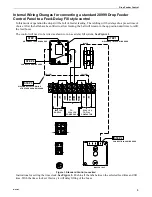
The 28999 Drop Feeder Control is designed to be used 

with a Chore-Time Drop Feeding System and Chore-
Time Flex-Auger

®

 System.

The control will automatically open the Drop Feeders, 

close the Drop Feeders, and start the fill system. The 
system may also be operated manually.

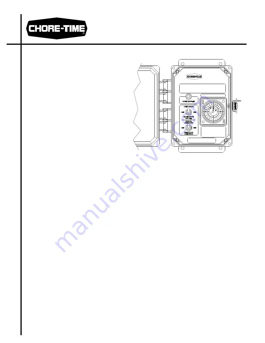
The components of the control are housed in a dust proof, 

water tight box. Liquid tight connectors must be used 
when wiring into the control. The cover must be latched 
in closed position unless switches or time clock is being 
adjusted.

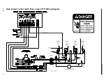
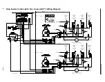
Wire the Drop Feeder Control, according to the 

appropriate wiring diagram.

Setting the Control

Unlatch and open front cover.

Time Clock operation

Set the desired feeding time(s) on clock by sliding out sufficient tabs to allow for auger run time. Slide out one 
additional tab for drop cycle (time required to open drops and close drops). Each tab represents 15 minutes. See 
“Time Clock Features and Operation” on page 5 for clock setting information.

The lower toggle switch should be in the TIME CLOCK OPERATION position.

The upper toggle switch should be in the OFF position.

How it Operates

When the switch on the time clock is activated by the tabs, all drops will open at the same time. The drops will 

automatically begin closing 15 seconds to 5 minutes after the clock is activated. This delay is adjustable 
inside the control panel.

In multiple lift applications the #1 lift will completely close, then #2, etc. until all drops have closed. At that 

time the fill system contactor and AUGER ENABLED Pilot Light will become energized and the fill system 
auger(s) will refill the drop boxes. The switch in the Drop Feeder Control Unit will stop the fill system(s). 
The fill system contactor and AUGER ENABLED Pilot Light will remain energized until the tabs no longer 
activate the Time Clock Switch.

CAUTION: Only use the number of time clock tabs needed to fill the system plus one extra tab. 

Manual Operation

Set the lower toggle switch to the MANUAL OPERATION position. The Time Clock is now disabled and the 
drops may be opened or closed using the upper toggle switch.

The upper toggle switch should be in the OFF position when not in use.

MA922-7D

Drop Feeder Control

Part Number 28999

CTB Inc.

P.O. Box 2000 • Milford, Indiana 46542-2000 • U.S.A.

Phone (574) 658-4101 • Fax (877) 730-8825

E-Mail: ctb@ctbinc.com • Internet: http//www.ctbinc.com

MA922F

August 2013

Summary of Contents for 28999

Page 1: ...F position How it Operates When the switch on the time clock is activated by the tabs all drops will open at the same time The drops will automatically begin closing 15 seconds to 5 minutes after the clock is activated This delay is adjustable inside the control panel In multiple lift applications the 1 lift will completely close then 2 etc until all drops have closed At that time the fill system ...

Page 2: ...e Drop Feeder Control Unit will stop the fill system Close the cover and secure latch to keep moisture and contamination from entering box and voiding warranty Drop Feeder Control Internal Wiring Diagram Feed Fill RED BLACK RED BLACK GREEN BLACK ORANGE RED BLUE YELLOW YELLOW ORANGE L2 L1 2526 286 230V 1PH TO FILL CONTACTOR ORG RED YELLOW ORANGE GREEN BLACK RED WH L1 L2 BLACK TO 230V 1PH SUPPLY BLK...

Page 3: ...need to be wired as shown to run as a delay fill system See Figure 1 Figure 1 Standard Control converted Instructions for setting the time clock See Figure 2 Push in all the tabs between the selected feed time and fill time With the time clock set this way it will delay filling of the boxes STEP 2 MA922 6 10 95 CONNECT BLACK WIRE HERE CONNECT RED WIRE HERE STEP 4 ORANGE 230V 1 PH SUPPLY STEP 3 DIS...

Page 4: ...D BLACK GREEN ORANGE RED BLUE ORANGE L2 L1 2526 286 230V 1PH TO FILL CONTACTOR ORG RED YELLOW ORANGE GREEN BLACK RED WH L1 L2 BLACK TO 230V 1PH SUPPLY BLK RED BLUE YELLOW BLACK BLACK YELLOW YELLOW RED BLACK BLUE ORANGE YELLOW ORANGE BLUE RED RED 230V 1PH POWER PACK RED BLACK YELLOW MA922 8 10 95 BLACK ...

Page 5: ...lockwise until the real time actual time of day is lined up with white arrow on inner clock face Do not turn the hand counter clockwise This will strip out the nylon gears and void your warranty Also never adjust the time clock by turning the outer dial Drop Feeder Control with Single Linear Actuator Wiring Diagram Time of Day AM PM Format Pull tabs as required for feeding cycle 1hr shown When adj...

Page 6: ...Drop Feeder Control 6 MA922F Drop Feeder Control with Multiple Linear Actuators Wiring Diagram ...

Page 7: ...Drop Feeder Control MA922F 7 Drop Feeder Control with One Linear Lift Wiring Diagram ...

Page 8: ...Drop Feeder Control 8 MA922F Drop Feeder Control with Two Linear Lifts Wiring Diagram ...

Page 9: ...Drop Feeder Control MA922F 9 Drop Feeder Control with One MULTI LIFT and One Tower Switch Wiring Diagram ...

Page 10: ...Drop Feeder Control 10 MA922F Drop Feeder Control Two MULTI LIFT Two Tower Switches Wiring Diagram ...

Page 11: ...ound Screw 4968 5 10 External Lock Washer 305 6 Corner Bracket 29013 1 7 Sheet Edge Insert 29878 8 Time Delay Relay 230 V 29890 9 Fuse Block 7588 10 5 amp Normal Blow Fuse 7001 11 Mounting Plate 28689 12 Copper Lug 28822 13 Terminal Block 7270 14 15 Strapping 29014 2 16 Mounting Adapter 25480 17 Time Clock 26795 18 Front Panel 28685 19 Toggle Switch 20135 20 Toggle Switch 29727 ...

Page 12: ...t in content that is different from the authoritative CTB published English version of the manual For current product installation and operation information please contact the customer service and or technical service departments of the appropriate CTB subsidiary or division Should you observe any questionable content in any manual please notify CTB immediately in writing to CTB Legal Department P...

Reviews: