background image

57" Assembled & Unassembled Direct Drive Endura® Fan

Installation

21

MV2491B

Screen Installation

(41561) Lag Screw angled 
slightly outward will allow 
for easier Screen removal 
when Screen Clip Washer 
(56671) is rotated as shown.

Center Screen on the wall opening and 
fasten with 8 Screen Clip Washers 
(56671) and (41561) Lag Screws as 
shown. 

Note: Some bowing of the 

Screen because of contact with power 
unit is normal.

Scre

en Ce

nte

red

Screen Centered

3/8" [9.5 mm]

(41561) 1/4 x 1-1/2 Lag Screw 

Loosen Lag Screw and Rotate Screen Clip Washer 
for easy Screen removal

(56671)
Screen Clip Washer

Item

Description

Part No.

1

1/4-10 x1.5 Lag Screw

41561

2

Screen Clip Washer

56671

3

59" Square Screen

56540

Lag Slightly Angled

2

1

Summary of Contents for Endura 56555-1 Series

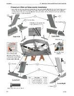
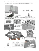
Page 1: ...f Fan performance and Fan damage 57 Assembled Unassembled Direct Drive Endura Fan 2491 001 07 20 2491 002 07 20 Fan Part No 56555 X Fan Bess Lab Test Phase Voltage Hz Full Speed RPM 56555 1 20084 1 230 60 630 56555 2 20085 3 230 60 630 56555 2 20086 3 230 50 630 Bess Lab test data available at http bess illinois edu type asp MV2491B September 2020 Installation and Operators Manual Installation and...

Page 2: ...ts 9 Blade Installation 9 Shroud and Shroud Components Installation 10 Bottom Shelf Installation 12 Attaching the Fan to the Wall 12 Keeping Fan Shroud edges straight 13 Attaching the Fan Shroud to the Wall 13 Cone Assembly 14 Installing the Orifice Frame 15 Cone Installation 15 Door Assembly and Installation 17 Grill Installation 18 Check Blade Tip Clearance 19 Door Spring Installation 19 Caulkin...

Page 3: ...e liable for any direct indirect incidental consequential or special damages which any purchaser may suffer or claim to suffer as a result of any defect in the Product Consequential or Special Damages as used herein include but are not limited to lost or damaged products or goods costs of transportation lost sales lost orders lost income increased overhead labor and incidental costs and operationa...

Page 4: ...X 53580 XX 53580 XX 53580 XX 53580 XX 53580 XX 53580 XX 53580 XX 2 57 DD Fan Component Pack 56559 XX 56559 XX 56559 XX 56559 XX 56559 XX 56559 XX 56559 XX 56559 XX 56559 XX 3 59 Square 1 25x2 Wire Screen 56540 56540 56540 56540 56540 56540 56540 56540 56540 4 57 Fan Blade 56494 XX 56494 XX 56494 XX 54530 XX 54530 XX 54530 XX 56494 XX 56494 XX 56494 XX 5 Motor 56501 56501 56704 56501 56501 56704 56...

Page 5: ...0 230 230 380 480 230 230 380 480 Cone Grill Ring Spacing 6 152mm 6 152mm 6 152mm 6 152mm 6 152mm 6 152mm 3 76mm 3 76mm 3 76mm Fan Blade Material Galv Galv Galv SS SS SS Galv Galv Galv Item Description Component Part No 1 57 DD Fan Sub Assembly 56555 1P 56555 1P 56555 3P 56555 1PS 56555 1PS 56555 3PS 56555 1P 56555 1P 56555 3P 2 57 Fan Cone Grill 53129 53129 53129 53129 53129 53129 55783 55783 557...

Page 6: ...er Drill 3 16 Drill Bit Expansion Clamp See Keeping Fan Shroud edges straight on page 13 3 8 Socket 1 2 Socket or Wrench Side Cutters Caulking Tools Needed and Supplies VFD Cross Reference Part Numbers Chore Time Part Number Invertek Model Number 56541 1 X ODE 3 120070 101A 56541 2 X ODE 3 120070 301A 56541 3 X ODE 3 140041 301A ...

Page 7: ...allation Planning Important Provide Shelter over Cones in areas where snow or ice could cause damage CTB Inc Warranty Does Not cover damage from external sources 57 3 8 145 7cm Max 55 1 4 140 3cm Min Important Fan mounting surface must be flat 5 12 7cm 60 1 16 152 5cm Minimum Spacing if sides of Cone are flattened 72 182 9cm Recommended Spacing 70 1 8 178 1cm 60 1 8 152 7cm 4 5 16 10 9cm 7 1 2 19 ...

Page 8: ... MV2491B Inspecting the Shroud Inspect the Shroud assembly for hardware as received Assembly Jig for Unassembled Fans For assembled versions skip to page 12 Installation 53626 Center V Post 48427 Magnet 53026 Magnet Side Plate 24 60 9cm 24 60 9cm 6 15 2cm Dia Motor ...

Page 9: ...ription Part No 1 57 DD Fan Motor Support 56502 2 5 16 18 x 3 4 Bolt 4412 11 3 5 16 Flg Nut 46764 46764 5 16 Flg Nut 4412 11 5 16 18 x 3 4 Bolt 1 3 2 1 4 Key Supplied with Motor Blade and 1 4 Key flush with end of Motor Shaft Apply Anti Seize to the Fan Blade Shaft and the Fan Blade bore before installing Blade Torque Fan Blade Bolt to 252 8 in lbs 28 47 9 Nm ...

Page 10: ...ect hole as shown Line up the Bolts with the Holes in the shroud and Motor Supports and set in place as shown Orient Shroud as shown with Decals in bottom left corner View from under Shroud 4412 28 5 16 18 x 1 Bolt Two Notches Two Notches 4 1 4 1 Notch 4 2 2 3 Item Description Part No 1 57 Cone Fan Bracket 53039 2 Upper Corner Support 56592 3 Lower Corner Support 56593 4 5 16 18 x 1 SS Bolt 4412 2...

Page 11: ...om Pivot Plate Bracket 53036 Fan Cone Cable 53399 1 and Eye Bolt 30663 as shown 46764 5 16 Flg Nut Item Description Part No 1 5 16 Flg Nut 46764 1 Item Description Part No 1 57 Fan Top Pivot Plate 53037 2 5 16 Flg Nut 46764 3 3 32 Fan Cone Cable 53399 1 4 5 16 18 x 2 Eye Bolt 30663 5 57 Fan Bottom Pivot Plate 53036 46764 5 16 Flg Nut 2 1 Pivot Plate Tab centered in V Post 2 3 4 Pivot Plate Tab cen...

Page 12: ...pening Outside of House 53338 Bottom Shelf Center of Bottom Shelf If the Shelf is too long Trim equal amounts from both ends This Flange must be straight after installation Tighten until Snug only Do not Deform the Bottom Shelf 1 1 7 17 8cm 2434 007b 03 2014 3 5 8 9cm Line up the four Holes in the Shroud with the Holes in the Bottom Shelf Set Fan Shroud on the Bottom Shelf ...

Page 13: ...the Fan to the Wall with 1 4 x 1 1 2 Lag Screws 41561 as shown Attach with a total of 20 Lag Screws Be sure sides of Shroud are straight and the wall mounting surface is flat Bowed sides or an uneven mounting surface can cause the fan blade to hit the orifice or excessive gaps between the Hyflo doors and the shroud A 600 Lb Hand Clamp can be used to straighten Shroud if necessary Keep edges of Shr...

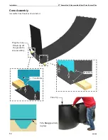
Page 14: ...ssembled Unassembled Direct Drive Endura Fan 14 MV2491B Cone Assembly Assemble Cone Panels as shown below Two Holes Prop the Cone Panels up off the ground to ease assembly One Hole Tabs Snap positively in place Tabs Up ...

Page 15: ...ing from the top of the Shroud using the hole in the Cone as shown 46764 54287 Rounded Tab on the Cone Orifice Frame Shown Gray for Clarity Important Line up the Seam in the Orifice Frame with one of the rounded Tabs on the Cone 53416 Orifice Frame 53611 Frame Bracket 54287 5 16 18 x 1 00 SS Shldr Bolt 46764 5 16 Flg Nut 30663 Eyebolt Seam in Orifice Frame ...

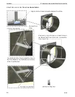
Page 16: ... the Cone to attach the Cone to the Cone Brackets Use the Bottom set of holes in the Cone Brackets If necessary slip a thin piece of metal between the Shroud and Cone and work it around the Cone to get it on Slip the Orifice Frame behind the Bottom Pivot Plate Bottom Pivot Plate 5 16 Flg Nut 46764 5 16 Flg Nut 46764 46764 5 16 Flg Nut ...

Page 17: ...y bottom out Doors are Left and Right specific Insert Door Pins into Bottom Pivot Plate Grab the Door in the Center Bow the Door outward and insert the Top Door Pin into the Top Pivot Bracket as shown Do not Overbow the Doors 53038 Door Pin Door Top Pivot Plate Bottom Pivot Plate Door Pin Spring Holes in Doors View of Back of Door View of Back of Door 53038 Door Pin ...

Page 18: ... Leg as shown 54287 46764 If it is desired to Mount Fans at the minimum spacing cutting the Grills is required as shown 46764 ST99070 46764 54287 Door Stop Cable Door Stop Cable even with the edge of Cone ST99070 3 8 SS Flat Washer 46764 5 16 Flg Nut 54287 5 16 18 x 1 00 Bolt Cut the Grill here Push the Cone Side in and use a Clamp to secure the Grill Wires 732 Clamp In Parts Package ...

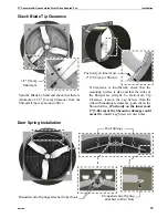
Page 19: ...heck that the mounting surface is flat and that the sides of the Shroud are straight To Gain more Tip Clearance remove the Lag Screws from the side with inadequate clearance push out on the Shroud orifice Push only on the inner most 2 5 08 cm of the Shroud or damage could occur Re install Lag Screws in new holes Push only on inner most 2 5 08 cm of Shroud 1 8 3mm Minimum Door Springs Rounded end o...

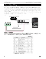
Page 20: ...ee the Invertek User Manual MV2493 at www choretime com documents Manuals Ventilation Fans Shutters 57 Inch Endura Fans MV2493 for mounting details and general wiring instructions Caulk Both Ends of the Bottom Shelf 10 0 VDC analog Speed Control Input 8 2 4m Cord supplied in Fan hardware package Attach Cord to Motor Supports with 3 Cable Ties 6635 Power Supply Line to Fan disconnect Important Matc...

Page 21: ...ing and fasten with 8 Screen Clip Washers 56671 and 41561 Lag Screws as shown Note Some bowing of the Screen because of contact with power unit is normal Screen Centered Screen Centered 3 8 9 5 mm 41561 1 4 x 1 1 2 Lag Screw Loosen Lag Screw and Rotate Screen Clip Washer for easy Screen removal 56671 Screen Clip Washer Item Description Part No 1 1 4 10 x1 5 Lag Screw 41561 2 Screen Clip Washer 566...

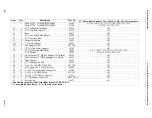
Page 22: ...ding 57 Direct Drive Endura Fans The following parameter have been changed from the drive default values Control Signal Wiring CT3 Analog Out Backup Box Relay Optional Parameter Sets No Defaults Description 1 2 P 01 60 Maximum Frequency Speed Limit rpm 630 630 P 03 5 Acceleration Ramp Time sec 3 3 P 04 5 Deceleration Ramp Time sec 30 30 P 05 0 Stop Mode Select 4 4 P 06 0 Energy Optimiser 1 1 P 07 ...

Page 23: ...n IMPORTANT Disconnect Power Prior To Maintaining Or Cleaning The Fan The fan may start automatically causing serious injury or death Service and repair of fans should be done only by a qualified technician Minimize contact of moisture or corrosive chemicals to the surfaces of the fan components to maximize fan life After washing fans operate fans long enough to remove moisture from all fan surfac...

Page 24: ...bled Unassembled Direct Drive Endura Fan 24 MV2491B Parts Numbers Itemized 1 Bottom Corner Brackets have one Notch Top Corner Brackets have two Notches 2 8 6 7 4 9 10 12 31 31 31 13 14 15 16 17 17 23 28 27 29 28 31 31 32 28 36 31 24 ...

Page 25: ...al 2527 90 All 13 4 57 DD Fan Motor Support 56502 All 14 1 57 Galv Bolted Hub Blade 56494 1 2 3 2T 3T 1U 2U 3U 1TU 2TU 3TU 57 SS Blade 54530 1S 2S 3S 1SU 2SU 3SU 15 2 Upper Corner 57 DD Fan Support 2 Notches 56592 All 16 2 Lower Corner 57 DD Fan Support 1 Notch 56593 All 17 4 Cone Bracket 53039 All 23 1 57 Fan Support Shelf 53338 All 24 4 5 16 18 x 1 00 HH 316SS Bolt 4412 28 All 27 1 59 Square 1 2...

Page 26: ...Unassembled Direct Drive Endura Fan Part Numbers Itemized continued MV2491B 26 Part Numbers Itemized continued 3 5 11 25 28 28 35 28 30 34 33 26 18 45 19 20 21 22 26 28 33 33 Used when Spacing Fans close together 37 ...

Page 27: ... 4 420SS Spring Pin 53038 All 30 1 5 16 18 x 2 SS Eye Bolt 30663 All 33 20 5 16 18 x 1 SS HXWH Bolt 54287 All 34 6 57 Fan Orifice Frame Brckt 53611 All 35 2 3 8 SS Flat Washer ST99070 All 37 1 70 OD Cone Grill with 3 Spacing 55783 1T 2T 3T 1TU 2TU 3TU 70 Cone Grill with 6 Spacing 53129 1 2 3 1S 2S 3S 1U 2U 3U 1SU 2SU 3SU 38 3 Cable Tie 6635 All 39 2 1 2 NPT Nylon Cord grip 23779 All 40 2 1 2 NPT G...

Page 28: ...Fans 35063 For additional parts and information contact your nearest Chore Time distributor or representative Find your nearest distributor at www choretime com contacts CTB Inc PO Box 2000 Milford Indiana 46542 2000 USA Phone 574 658 4101 Fax 877 730 8825 Email choretime choretime com Internet www choretime com ...

Reviews: