background image

Fan Assembly/Installation

36" Galvanized Belt Drive HYFLO® Fans

4

MV2386E

Belt Installation

Guide the Belt through the Opening in the Motor Support Bracket and loop it over the Motor Sheave. Guide 

the Belt around the Tensioner Sheave and push on it to get enough slack to put the Belt on the Driven Sheave 

as shown in


Figure 10

. Make sure the Belt does not rub against the Motor Support Bracket.

3

Item

Description

1

Belt

2

Motor Sheave

3

Tensioner Sheave

4

Driven Sheave

1

32

4

Figure 10.  Installing the Belt

Cone Assembly and Installation

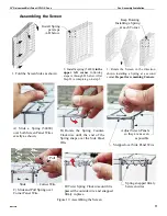
Figure 11.  Assembling Cone Panels

Slots in Cone Panel

C-Shaped Drain Tab

31

Item

Description

1

Cone Panel

Wrong! Cone Panel is upside down

Lay a Cone Panel down (Drain Tab at the bottom and slots to the left) and Prop the end 

up (Slotted end) with a 2 x 4 board.

Step 1:

Summary of Contents for Hyflo 53096-52

Page 1: ...Vertical Dim of Cone 1 2 54cm 3 Height Outside of Flanges 45 1 2 115 57cm 4 Rough Opening Width 43 109 22cm 5 Rough Opening Height 42 1 2 107 95cm 6 Minimum Spacing 3 1 2 8 89cm 7 Outside Diameter of...

Page 2: ...push them into the slots in the Fan Housing Panels and rotate them forward until they lock into place as shown Slide the Fan forward flush with the rough opening making sure that the Clips do not fall...

Page 3: ...4 SS Lag Screw 2 Nylon Washer 3 Screen Retainer B B A A Motor Installation Rotate the Motor Support Bracket into the upright position by removing the Upper Carriage Bolt and Nut and loosening the Low...

Page 4: ...ve as shown in Figure 10 Make sure the Belt does not rub against the Motor Support Bracket 3 Item Description 1 Belt 2 Motor Sheave 3 Tensioner Sheave 4 Driven Sheave 1 3 2 4 Figure 10 Installing the...

Page 5: ...ne Panels together with 4 5 16 x 1 2 Hex Bolts threaded from inside the finished Cone Do not tighten down the Nuts at this time Leave the Nuts loose until the Cone is attached to the Fan Stand the Pan...

Page 6: ...Do not install Nuts at this time These Bolts will be used later to attach the Cone Brackets to the Cone Assembly Use 2 5 16 x 1 1 4 Bolts Item 3 and 2 5 16 Flange Nuts Item 4 to attach the Ring to th...

Page 7: ...m 1 until it is flush with the Cone and secure it with a 5 16 18 Carriage Bolt Item 3 and Flange Nut Item 4 as shown Item Description 1 Bottom Grill Eyehook 2 Door Stop Cable Nylon Cable 3 5 16 18 x 6...

Page 8: ...as shown Attach the top of the Cone to the Cone Brackets Item 2 with the Bolts that were previously threaded through the Ring and Cone and secure with 5 16 Flange Nuts Item 3 Only hand tighten the Nut...

Page 9: ...the Spring Mounting Bracket Included in the Parts Package Step 1 3 4 Hook the rounded ends of the Door Springs onto the Spring Mounting Bracket Stretch the Door Springs out and hook them in the 3 32...

Page 10: ...ans 10 MV2386E Cone Drain Tabs The Fan Cone is designed with a C Shaped Drain Tab located at the back of the Bottom Cone Panel Use a screw driver to push the Drain Tab out as shown in Figure 18 below...

Page 11: ...er the Side Panel Wire Snapped over Side Panel Wire C Slide and Pull Spring over Corner Panel Wire D Twist Spring Clockwise until it is passed the outside wire and snapped firmly in place Spring snapp...

Page 12: ...r Clarity Screen Wire Item Description 1 Screen 2 Screen Clip 3 Screen Retainer 3 1 3 2 3 2 3 3 Figure 20 Installing the Screen Rotate the four Screen Retainers to capture the Screen Hang the Screen I...

Page 13: ...s connected for counter clockwise rotation viewing the back of the motor opposite the shaft end 5 Follow local state and national electrical codes for wiring Cut out one section of the Screen to route...

Page 14: ...emized Parts 1B 1A 2 3 4 5 14 23 x8 25 3 3 48 49 26 x4 26 x8 x4 26 x4 25 x4 26 x4 50 44 47 x4 25 x8 x8 x16 21 23 x8 See Page 14 24 x16 42 x4 Itemized Parts 36 Galvanized Belt Drive HYFLO Fans 14 MV238...

Page 15: ...in Door Assembly 50311 Item Qty Part Description Part No 19 1 Fan Description Decal 39002 XXX 21 1 44 Wire Screen 53103 23 9 1 4 10 x 1 75 Lag Screw 51039 24 16 1 4 14 x 1 2 HXWH Screw 48439 25 34 5 1...

Page 16: ...Itemized Parts Continued 35 20 51 52 36 38 46 45 41 16 37 40 50 39 54 x 4 x 4 x 8 x 8 26 25 x 4 50 x 2 26 x 2 26 17 x 4 Itemized Parts Continued 36 Galvanized Belt Drive HYFLO Fans 16 MV2386E...

Page 17: ...0 Magnet 48427 39 2 1 8 x 40 Pop Rivet 48936 40 10 1 2 Foam Tape 48425 41 1 46 75 Cable Assembly 50618 3 45 1 Door Spring Support 49450 46 2 055 x 50 x 11 Spring 49629 51 4 1 4 20 Serrated Flange Nut...

Page 18: ...Belt will cause a substantial drop in Fan perfor mance or it can break and cause Fan failure If a Belt rides below the Sheave edge replace the belt See Figure 22 below Bad Belt Good Belt 1747 054 04...

Page 19: ...vent contamination from entering the bearing Use a high quality lithium based NLGI 2 grease such as Shell Gadus S2 V100 2 Do not use incompatible greases containing aluminum barium calcium bentonite c...

Page 20: ...ME shall not be liable for any direct indirect incidental consequential or special damages which any purchaser may suffer or claim to suffer as a result of any defect in the Product Consequential or S...

Page 21: ...36 Galvanized Belt Drive HYFLO Fans Warranty MV2386E 21 This Page left blank intentionally...

Page 22: ...with such changes inasmuch as such changes result in content that is different from the authoritative CTB published English version of the manual For current product installation and operation informa...

Reviews: