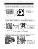
background image

Safety Information

48" and 52" HyfloTM Fans Installation and Operators Instruction Manual

10

MV1747D

Carefully read all safety messages in this manual and on your equipment safety signs. Follow recommended 
precautions and safe operating practices. Keep safety signs in good condition. Replace missing or damaged 
safety signs.

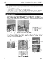
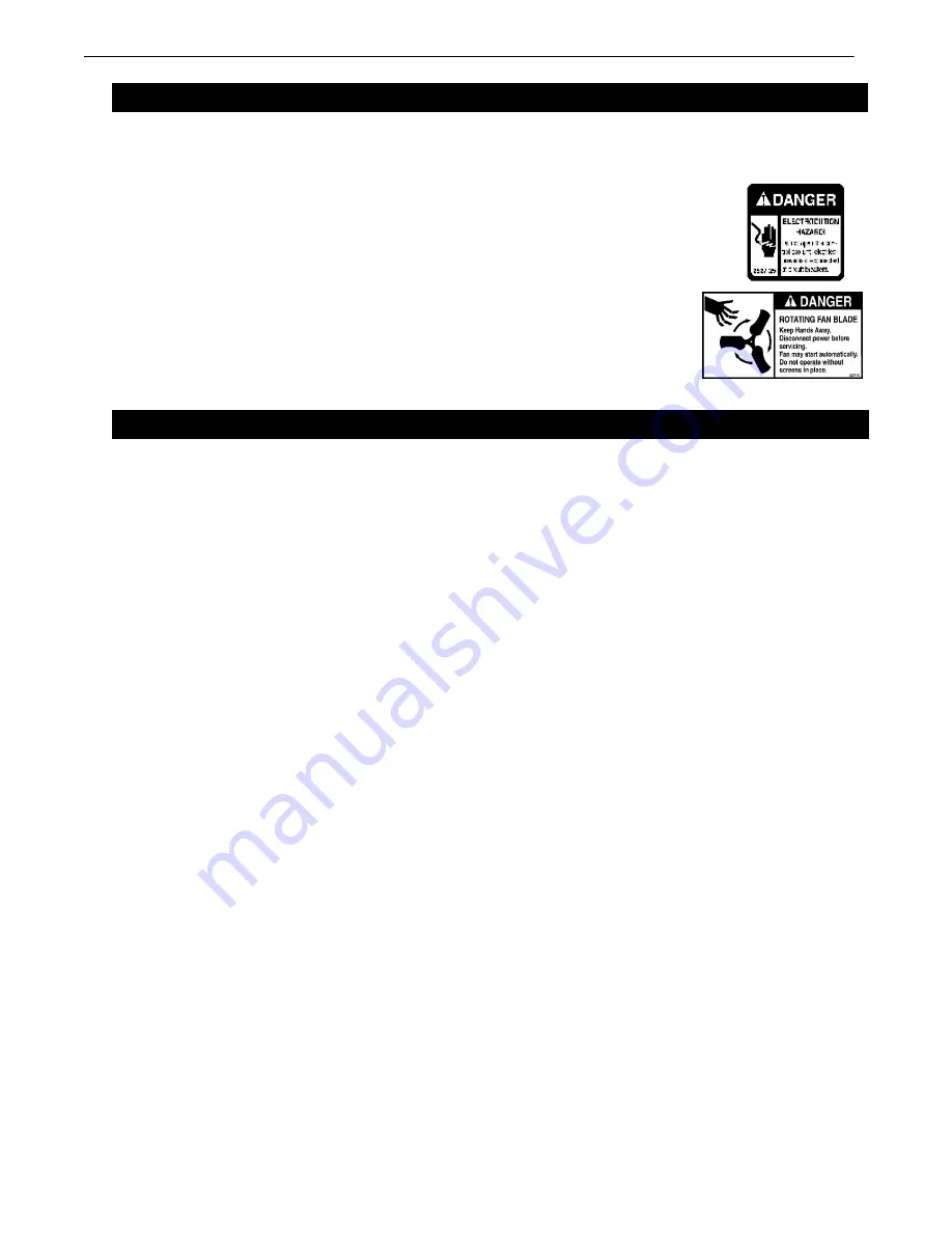
DANGER: Electrical Hazard

Disconnect electrical power before inspecting or servicing equipment Ground 
all electrical equipment for safety. All electrical wiring must be done by a 
qualified electrician in accordance with local and national electric codes. 
Ground all non-current carrying metal parts to guard against electrical shock. 
With the exception of motor overload protection, electrical disconnects and 
over current protection are not supplied with the equipment.

DANGER: Rotating Fan Blade

Keep Hands away. Disconnect power before servicing. Fan may start
automatically. Do not operate the Fan without the screens in place. Disregard
to these things will cause serious injury including death.

Chore-Time Equipment

 (“Chore-Time”) warrants each new Chore-Time product manufactured by it to be free from 

defects in material or workmanship for one year from and after the date of initial installation by or for the original 
purchaser. If such a defect is found by the Manufacturer to exist within the one-year period, the Manufacturer will, at 
its option, (a) repair or replace such product free of charge, F.O.B. the factory of manufacture, or (b) refund to the 
original purchaser the original purchase price, in lieu of such repair or replacement. Labor costs associated with the 
replacement or repair of the product are not covered by the Manufacturer.

Conditions and Limitations

1. The product must be installed by and operated in accordance with the instructions published by the 

Manufacturer 

or Warranty will be void

.

2. Warranty is void if 

all components

 of the system are not original equipment supplied by the 

Manufacturer

.

3. This product must be purchased from and installed by an authorized distributor or certified representative thereof or 

the Warranty will be void.

4. Malfunctions or failure resulting from misuse, abuse, negligence, alteration, accident, or lack of proper maintenance 

shall not be considered defects under the Warranty.

5. This Warranty applies only to systems for the care of poultry and livestock. Other applications in industry or 

commerce are not covered by this Warranty.

The 

Manufacturer

 shall not be liable for any 

Consequential or Special Damage

 which any purchaser may suffer or 

claim to suffer as a result of any defect in the product. 

“Consequential”

 or 

“Special Damages”


as used herein include, 

but are not limited to, lost or damaged products or goods, costs of transportation, lost sales, lost orders, lost income, 
increased overhead, labor and incidental costs and operational inefficiencies.

THIS WARRANTY CONSTITUTES THE MANUFACTURER’S ENTIRE AND SOLE WARRANTY AND THIS 
MANUFACTURER EXPRESSLY DISCLAIMS ANY AND ALL OTHER WARRANTIES, INCLUDING, BUT 
NOT LIMITED TO, EXPRESS AND IMPLIED WARRANTIES AS TO MERCHANTABILITY, FITNESS FOR 
PARTICULAR PURPOSES SOLD AND DESCRIPTION OR QUALITY OF THE PRODUCT FURNISHED 
HEREUNDER.

Chore-Time Distributors are not authorized to modify or extend the terms and conditions of this Warranty 
in any manner or to offer or grant any other warranties for Chore-Time products in addition to those terms 
expressly stated above. An officer of CTB, Inc. must authorize any exceptions to this Warranty in writing. 
The Manufacturer reserves the right to change models and specifications at any time without notice or 
obligation to improve previous models.

Contact your nearby Chore-Time distributor or representative for additional parts and information.

CTB Inc.

P.O. Box 2000 • Milford, Indiana 46542-2000 • U.S.A.

Phone (574) 658-4101 • Fax (877) 730-8825

E-Mail: ctb@ctbinc.com • Internet: http//www.ctbinc.com

Printed in the U.S.A.

Safety Information

Warranty

Summary of Contents for Hyflo

Page 1: ...16 04 03 Item 48 Hyflo 52 Hyflo 1 41 7 8 106 36 cm 44 111 76 cm 2 59 149 9 cm 64 162 56 cm 3 5 1 8 13 02 cm 5 1 8 13 02 cm 4 12 35 31 37 cm 12 35 31 37 cm 5 2 5 16 5 87 cm 4 1 8 10 48 cm 3 2 Figure 1 Fan Dimensions 4 1 5 MV1747 017 04 03 3 2 3 2 Planning the layout of the spacing between Fans is very important Spacing too close together will cause interference between the discharge Cones The Rough...

Page 2: ...Note that the Nuts go outside the Posts Remove the Motor from the Crate and attach it to the Motor Support Bracket with 4 5 16 Carriage Bolts and 4 5 16 Flange Nuts as shown Belt Installation Guide the Belt through the Opening in the Motor Support Bracket and loop it over the Motor Sheave Guide the Belt around the Tensioner Sheave and push on it to get enough slack to put the Belt on the Driven Sh...

Page 3: ...e panels up on edge and curl the Cone around with the smaller diameter of the Cone up as shown below Assemble the final Panels together and allow the Cone to take its shape If the Cone is assembled correctly the Tabs should all be on the Inside of the finished Cone Fasten the Cone Panels together with 4 5 16 x 1 2 Hex Bolts Threaded in from the inside of the finished Cone as shown in Figure 7 Cone...

Page 4: ... Holes located on both sides near the Door Center Brace as shown below Note that the Nuts go on the outside of the Cone Turn the Cone over to install the Grill Orient the Grill so the Leg with the bent spokes at the Center of the Grill is Parallel with the Center Door Hinge and that the bent Spokes are either above or below center Not to the left or right See Figure 10 Install the Rubber Grommet 3...

Page 5: ...nd tighten the Nuts at this time Working around the Fan Orifice in a circular motion Slide the Cone over the Fan Orifice The Cone will Fit snug over the Fan Orifice Use the Bolts previously threaded through the Ring and Cone and the 5 16 Flange Nuts to secure the bottom of the Cone to the Fan Figure 12B Use a Level and rotate the Cone until the Door center rail is Vertical Now tighten all Hardware...

Page 6: ...e cord out of the Fan This will allow for the Screen to be removed without interfering with the Cord See Figure 13 Attach the cord to the Wall using a Lag Screw and Cord Clip Allow enough slack in the cord to form a drip loop for moisture to fall away from the cord and not into the motor Hang the Rear Screen on the four tabs located in the corners of the Fan Mounting Flange Position the Screen so ...

Page 7: ...mature Belt and Bearing wear With a new Belt the Idler Sheave indicator mark should line up with the third notch in the Ten sioner Housing See Figure 16 Keep Shutters Blades and Housing clear of obstacles for best air performance The motor and Fan Shaft Bearings are pre lubricated Grease zerks are provided on the fan shaft bearings for installations where re lubrication is needed Add only a small ...

Page 8: ...M Fans Installation and O perators Instruction Manual 8 MV1747D 48 HyfloTM Itemized Parts 3 10 3 4 3 30 3 9 3 16 3 18 3 12 3 15 3 14 3 7 3 6 3 19 3 3 3 5 3 8 3 11 3 13 3 25 3 22 3 23 3 21 3 20 3 26 3 27 3 33 3 29 3 2 3 17 3 32 3 31 3 24 3 1 3 28 ...

Page 9: ... 51 52 Sheave Driven AK94 40274 21 22 41 42 40274 21 22 41 42 12 Hyflo Top Panel 48671 All 48685 All 13 Hyflo R H Side Panel 48672 2 All 48684 2 All 14 Hyflo L H Side Panel 48672 1 All 48684 1 All 15 Hyflo Bottom Panel 48673 All 48686 All 16 Sheave Driver AK27 1381 23 Sheave Driver AK30 8773 21 22 41 42 8773 21 22 41 42 Sheave Driver AK32 48504 51 52 48504 51 52 17 Screen Clip 36729 All 36729 All ...

Page 10: ... ifall components of the system are not original equipment supplied by the Manufacturer 3 This product must be purchased from and installed by an authorized distributor or certified representative thereof or the Warranty will be void 4 Malfunctions or failure resulting from misuse abuse negligence alteration accident or lack of proper maintenance shall not be considered defects under the Warranty ...

Reviews: