
Fan Assembly/Installation
48" and 52" HyfloTM Fans Installation and Operators Instruction Manual
2
MV1747D
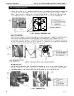
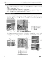
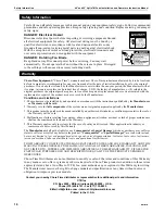
Remove the Fan from the Crate and Install into Wall opening. The Danger Decals should be located at the
bottom of the Fan as
shown below
. In the holes at the side center locations Use 1 Lag Screw, 2 Nylon
Washers, and 1 Screen Clip to attach the Fan to the wall
(See Figure 2)
. These Screen Clips will later be
used to hold the Screen on. Install Lag Screws in the remaining 6 locations as shown in
Figure 2
.
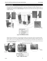
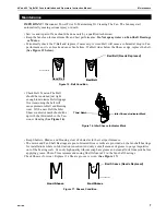
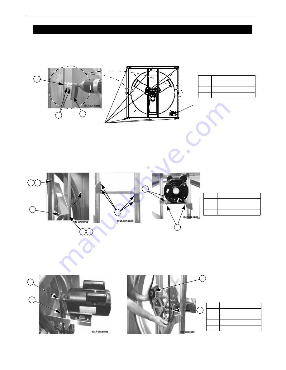
Motor Installation
Rotate the Motor Support Bracket into the upright position by removing the
Upper
Carriage Bolt and Nut
and loosening the
Lower
Bolt and Nut
(See Figure 3)
. Rotate the Motor Support Bracket until it is
perpendicular to the Fan Posts and fasten with (4) 5/16 Carriage Bolts and (4) 5/16 Flange Nuts.
Note that
the Nuts go outside the Posts
. Remove the Motor from the Crate and attach it to the Motor Support Bracket
with (4) 5/16 Carriage Bolts and (4) 5/16 Flange Nuts
as shown
.
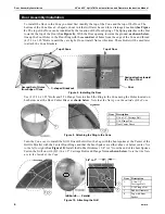
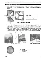
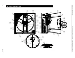
Belt Installation
Guide the Belt through the Opening in the Motor Support Bracket and loop it over the Motor Sheave. Guide
the Belt around the Tensioner Sheave and push on it to get enough slack to put the Belt on the Driven Sheave
as shown in
Figure 4
. Make sure the Belt does not rub against the Motor Support Bracket.
Fan Assembly/Installation
17 47 - 00 5 0 3/ 04
Decals at Bottom
Lag Screw Locations
Item
Description
1
1/4 x 1-1/2" Lag Screw
2
Nylon Washer
3
Screen Clip
Figure 2. Installing Fan in Wall Opening
3
2
3
3
3
1
Figure 3. Attaching the Motor Support Bracket and Motor
Item
Description
1
Motor Support Bracket
2
5/16 Carriage Bolt
3
5/16 Flange Nut
Lower Nut and Bolt
Hidded by Fan Post
3
2
3
1
3
3
3
3
2
3
3
3
2
3
2
Upper
3
Item
Description
1
Belt
2
Motor Sheave
3
Tensioner Sheave
4
Driven Sheave
1
3
2
3
4
Figure 4. Installing the Belt


