
48" and 52" HyfloTM Fans Installation and Operators Instruction Manual
Cone Assembly
MV1747D
3
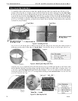
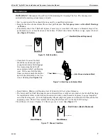
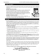
The Cone Panels can be identified by the number of notches at the edge of each Panel. Begin the Cone
assembly by laying the Panel with
no tabs
on a couple of boards with the one notch end to the left and with
the
Knock-out
at the Bottom
as shown in Figure 6
. Insert the tabs into the slots on the edge with the same
number of notches.
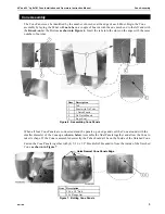
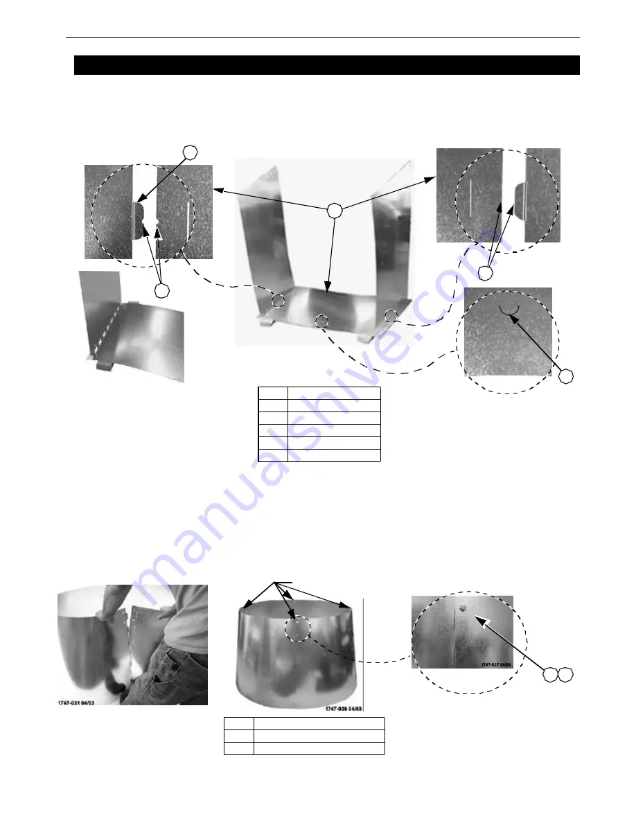
When all four Cone Panels are connected stand the panels up on edge and curl the Cone around with the
smaller diameter of the Cone up as
shown below
. Assemble the final Panels together
and allow the Cone to
take its shape. If the Cone is assembled correctly the Tabs should all be on the Inside of the finished Cone.
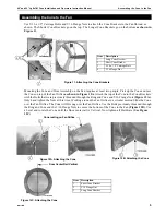
Fasten the Cone Panels together with (4) 5/16 x 1/2" Hex Bolts Threaded in from the inside of the finished
Cone
as shown in Figure 7
.
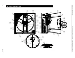
Cone Assembly
3
3
3
3
4
Item
Description
1
Tab
2
Panel with No Tabs
3
1 Notch Panels
4
No Notch Panels
5
Knock-out
Figure 6. Assembling Cone Panels
3
1
2
3
5
Holes Nearest Cone Panels Edge
3
2 3
1
Item
Description
1
5/16 x 1/2" Bolt
2
5/16 Flange Nut
Figure 7. Bolting Cone Panels


