
48" and 52" HyfloTM Fans Installation and Operators Instruction Manual
Assembling the Cone to the Fan
MV1747D
5
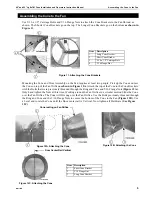
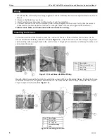
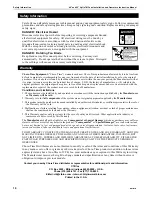
Use 5/16 x 1/2" Carriage Bolts and 5/16 Flange Nuts to attach the Cone Brackets to the Fan Shroud as
shown. The Shorter Cone Brackets go on the top. The Longer Cone Brackets go on the bottom
as shown in
Figure 11
.
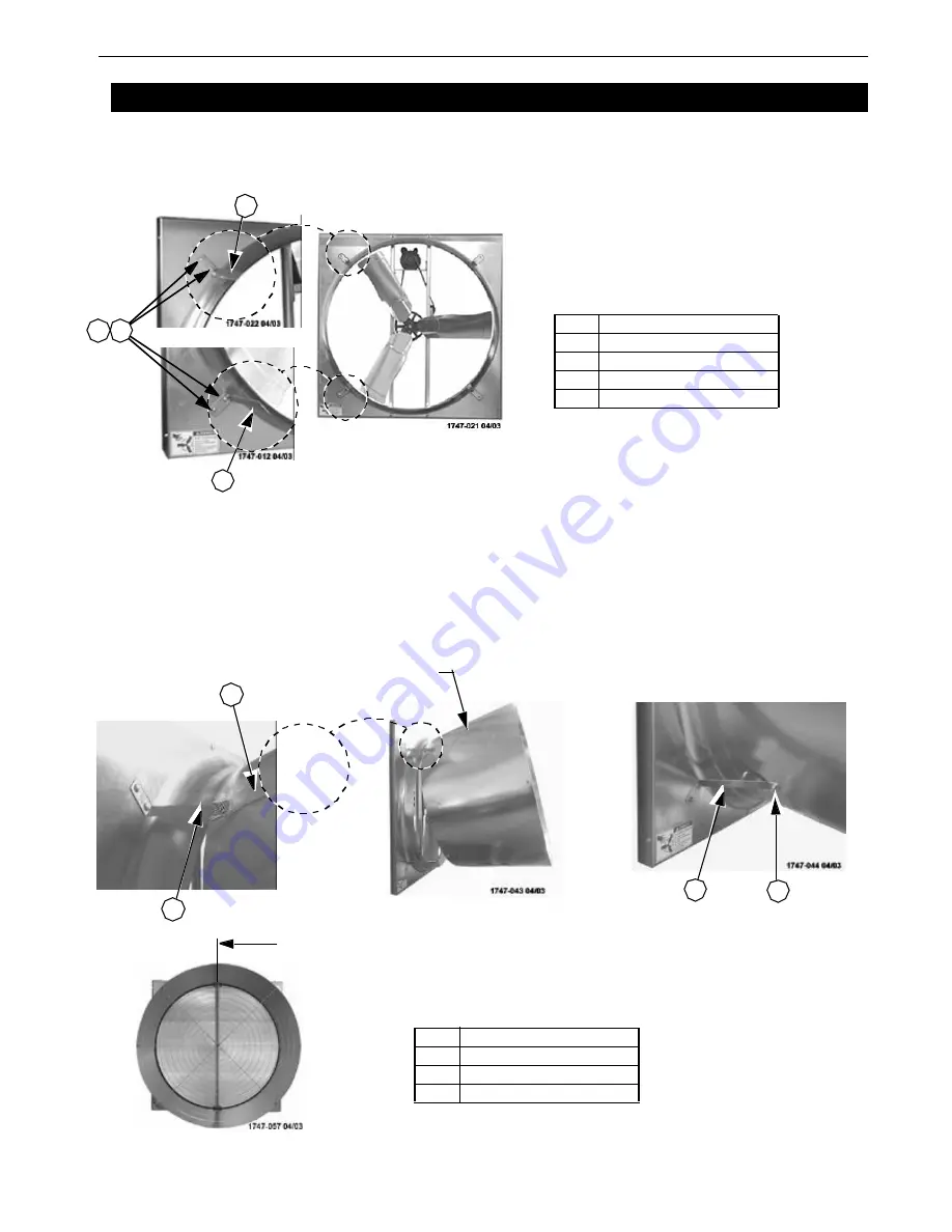
Mounting the Cone and Door Assembly on the Fan requires at least two people. Pick up the Cone and rest
the Cone on top of the Fan Orifice
as shown in
Figure 12A
. Attach the top of the Cone to the Cone Brackets
with the Bolts that were previously threaded through the Ring and Cone and 5/16 Flange Nuts
(Figure 12A)
.
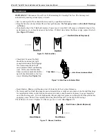
Only hand tighten the Nuts at this time. Working around the Fan Orifice in a circular motion Slide the Cone
over the Fan Orifice. The Cone will Fit snug over the Fan Orifice. Use the Bolts previously threaded through
the Ring and Cone and the 5/16 Flange Nuts to secure the bottom of the Cone to the Fan
(Figure 12B)
. Use
a Level and rotate the Cone until the Door center rail is Vertical. Now tighten all Hardware
(See Figure
12C)
.
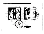
Assembling the Cone to the Fan
Figure 11. Attaching the Cone Brackets
Item
Description
1
Long Cone Bracket
2
Short Cone Bracket
3
5/16 x 1/2" Carriage Bolt
4
5/16 Flange Nut
3
2
3
1
3
3
3
4
3
2
3
1
Cone resting on Fan Orifice
3
3
3
2
Figure 12B. Attaching the Cone
Item
Description
1
Short Cone Bracket
2
5/16 Flange Nut
3
Long Cone Bracket
Door Center Rail Vertical
Figure 12A. Attaching the Cone
Figure 12C. Attaching the Cone


