background image

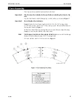
Cone Assembly

48'' Belt Drive Cone Fan

12

MV1600B

With the help of an assistant, lift the Cone Assembly to the Fan Shroud.

Slide the smaller end of the Cone Assembly over the Fan Shroud. Rotate the Cone 
Assembly to align the Panel Joints with the Cone Hanger Brackets. 

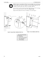
Secure the Cone Assembly to the Cone Hanger Brackets using (1) 5/16''-18 carriage 
bolt, 3/8'' lock washer, and 5/16''-18 hex nut. See 

Figure 8 and 9

.

Tighten all the hardware after the cone assembly is secure and in place.

MV1600-013 6/99

1

2

4

3

5

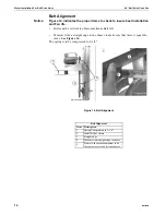
Hanger Bracket Installation

Item

Description

1

Fan Assembly

2

5/16-18 x 5/8'' Carriage Bolt

3

Cone Hanger Bracket

4

5/16-18'' Hex Nut

5

3/8'' Lock Washer

Figure 8. Hanger Bracket Installation (Side View)

MV1600-014 6/99

1

2

3

4

5

6

Figure 9. Cone Installation (Side View).

Summary of Contents for MV1600B

Page 1: ...48 Belt Drive Cone Fan Installation Operator s Instruction Manual MV1600 1 6 99 MV1600B August 1999...

Page 2: ...onsidered defects under this warranty 5 This warranty applies only to systems for the care of poultry and livestock Other applications in industry or commerce are not covered by this warranty Chore Ti...

Page 3: ...D I Safety Information 6 C D I Safety Alert Symbol 6 Follow Safety Instructions 6 Decal Placement 7 Technical Information 8 C I Fan Installation 9 C I Fan Dimensions 10 I Fan Assembly 11 I Cone Assem...

Page 4: ...rk for safety and manufacturing issues CE is required only on equipment sold in Europe Chore Time Equipment recognizes CE Mark and pursues compliance in all applicable products Fill in the CE Mark ser...

Page 5: ...l SAFETY information Metric measurements are shown in millimeters and in square brackets unless otherwise specified equals inches and equals feet in English measurements Examples 1 25 4 4 1 219 Option...

Page 6: ...ction with the safety alert symbol to identify the severity of the warning DANGER indicates an imminently hazardous situation which if not avoided WILL result in death or serious injury WARNING indica...

Page 7: ...source be available for confinement buildings in case of power failure Motor choices and specifications are provided in the Parts List section of this manual See Page 23 Fan Motor specifications Impo...

Page 8: ...med opening left to right Allow the Fan Housing to set on the bottom of the framed opening Secure the Fan Assembly to the framed opening using the included 1 4 x 1 3 4 Lag Screws starting with the cen...

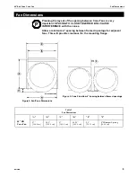
Page 9: ...a minimum 4 spacing between framed openings for adjacent fans This will provide clearance for the mounting flange Fan Dimensions MV1600 003 6 99 MV1600 006 6 99 Table 2 Fan Dimensions A B C D E F 48 B...

Page 10: ...Fan by sliding the Corner Flange Angle under all edges of Flange Corners secure with lag screws Fan Assembly Blade Rotation MV1600 B01 8 99 4 4 Figure 6 Fan Assembly side view 1600 010 6 99 Item Desc...

Page 11: ...18 hex nuts per joint Only install hardware at the locations shown in Figure 7 Set the Cone Side Panels up and align the ends to create the cone shaped housing Loosely secure the ends similar to the...

Page 12: ...Assembly to the Cone Hanger Brackets using 1 5 16 18 carriage bolt 3 8 lock washer and 5 16 18 hex nut See Figure 8 and 9 Tighten all the hardware after the cone assembly is secure and in place MV1600...

Page 13: ...he 5 16 18 carriage bolts 3 8 lock washers and 5 16 18 hex nuts See Figure 10 This will help maintain the shape of the Cone Assembly while it is being secured to the Fan Shroud MV1600 9B 6 99 1 4 3 5...

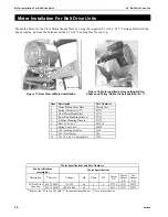
Page 14: ...tor Installation MV1600 2 6 99 2 1 3 4 5 7 8 6 9 Mount the Motor to the Pivot Motor Mount Plate by using the supplied 5 16 18 x 625 Carriage Bolt with the heads coming up from the bottom and the 5 16...

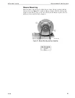
Page 15: ...own Insert the key provided with the motor as shown in Figure 13 to lock the Sheave in place Once the belt has been aligned torque the set screw to 150 165 in lbs to secure Sheave in place Do not tigh...

Page 16: ...lt Life Measure from a straight edge to the sheave to make sure that there is equal dis tance See Figure 14 The spring is to be compressed to 2 1 4 MV1600 5 6 99 1 MV1600 6 6 99 Belt Alignment Item De...

Page 17: ...nected for counter clockwise rotation viewing the opposite shaft end of the motor Important Follow local state and national electrical codes for wiring 6 Attach the cord to the top panel of the fan us...

Page 18: ...upplied toward the upper corners of fan using the Knockouts and cord bushing See Figure 16 Note For both the Aluminum and or Plastic Shutter route the motor cord through the Knockouts as shown in Figu...

Page 19: ...tom Panel Slots lean the Shutter back and lock it in place by rotating the Shutter Clips Check the Shutter for proper operation the shutter must be able to open and close freely without obstructions S...

Page 20: ...e belt from slipping Keep Shutters Blades and Housing clear of obstacles for best air performance The Motor and Fan Shaft Bearings are prelubricated Grease Zerks are provided on the Fan Shaft Bearings...

Page 21: ...Manual Itemized 48 Belt Dr ive Cone Fan Manual 21 Itemized 48 Belt Drive Cone Fan Blade Rotation MV1600 001 8 99 1 2 3 4 5 7 8 1 14 15 14 16 17 29 28 9 24 25 18 6 15 26 31 30 21 22 20 23 13 27 11 12...

Page 22: ...9 48 Shutter Mounting Brace 43673 26 Decal 48 SW Cone Fan BD 39002 206 10 Post 48 x 12 5 Fan 43688 27 Grill 37630 11 Plate Pivot Motor Mount 43713 28 Shutter Plastic 38029 12 Bracket Pivot Plate Mount...

Page 23: ...48 Belt Drive Cone Fan Motor Specifications and Parts Listing MV1600B 23 This page left blank for your notes...

Page 24: ...work Built to last Contact your nearby Chore Time distributor or representative for additional parts and information CTB Inc P O Box 2000 Milford Indiana 46542 2000 U S A Phone 219 658 4101 Fax 800 3...

Reviews: