SUPER-Selector
‘
PT Control
Page 4
Programming the SUPER-Selector PT
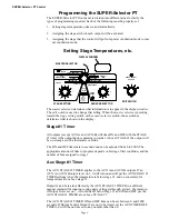
The SUPER-Selector PT front panel is divided into different areas to clarify the
types of programming required. Each of the following must be properly set.
1. Setting stage temperatures, timers, and alarm limits.
2. Assigning the stage at which each output will be activated.
3. Assigning the stage that the control will go from power ventilation mode to tun-
nel ventilation mode.
Setting Stage Temperatures, etc.
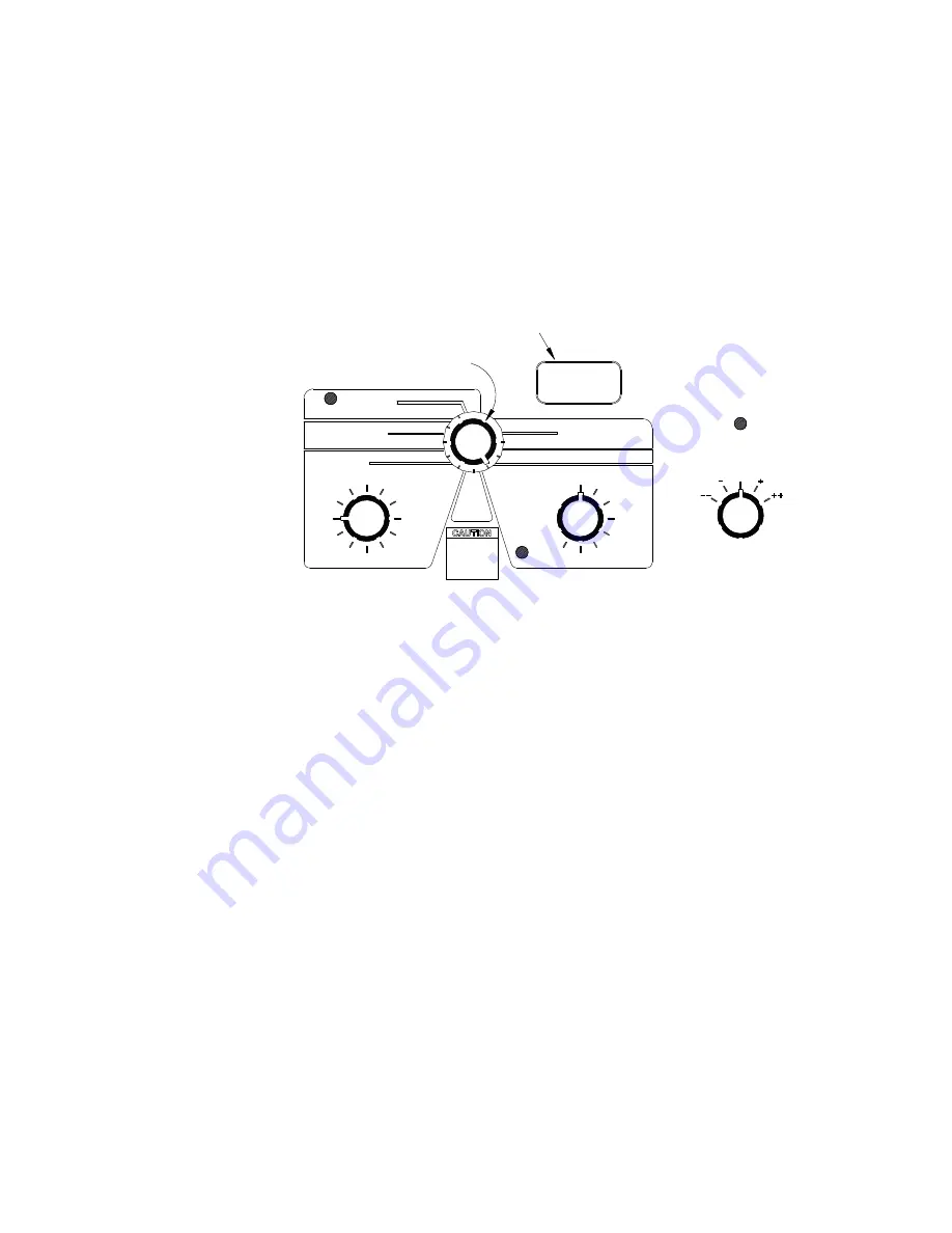
The master selector determines what information is to appear in the display window.
The edit switch is used to change that setting. When the master selector is pointing
toward the stage setting switch or the sensor selector switch, those switches
determine what is shown in the display.
Stage #1 Timer
All outputs (except AUX-A and AUX-B) will time ON and OFF with the STAGE
#1 timer if the output knob is pointing towards 1. Above STAGE #1 the output will
be on steady as with a thermostat override.
The ON and OFF timers are in seconds and can be adjusted from 0 to 2000. The
appropriate amount of time to program depends on bird age, litter condition, and the
number of fans assigned to stage 1
Aux Stage #1 Timer
The AUX STAGE #1 TIMER applies to the AUX A and AUX B outputs. If an
AUX A or AUX B output is set on 1, it will turn on and off per the AUX STAGE #1
TIMER settings when the temperature is below stage #1, and on constantly for
temperatures at or above stage #1.
Outputs I and J are also affected by the AUX STAGE #1 TIMER in a different
manner intended for running cooling pads or foggers through a timer. For instance,
if Output I were set on 7, it would be off below stage #7 and ON and OFF per the
AUX STAGE #1 TIMER at or above STAGE #7.
The AUX STAGE #1 TIMER ON and OFF time can be set between 0 and 2000
seconds. If Output I and/or Output J are not to be timed, set the AUX TIMER OFF
TIME to 0 with the on time set to any number other than 0.
GREEN - NORMAL
0
SET
3
2
5
6
RED - EDIT
ON TIME
OFF TIME
ON TIME
OFF TIME
LOW ALARM TEMP
HIGH ALARM TEMP
READ SENSOR
8
FAILED
SENSOR
6
5
OFFSETS
TEMPERATURE
9
8
7
SET
POINT
TEMP
AUX
3
2
STAGES
H1
H2
1
ALARM
4
10
STAGE #1 TIMER
TIMER
1
7
CONTROL SENSOR
STAGE #1
4
DISPLAY WINDOW
MASTER SELECTOR
STAGE SETTING
SENSOR SELECTOR
EDIT SWITCH
MV1041-2 10/96
Set Point
Whenever
Backups
Is Changed
Reset

