background image

36 RH Corsair 

 Owner’s Manual 

Model Year 2014 

CHRIS-CRAFT CORPORATION   

8161 15

TH 

STREET EAST SARASOTA FL 34243 USA  

1-(941) 351-4900  www.chriscraft.com


Summary of Contents for 2014 36 RH Corsair

Page 1: ...36 RH Corsair Owner s Manual Model Year 2014 CHRIS CRAFT CORPORATION 8161 15TH STREET EAST SARASOTA FL 34243 USA 1 941 351 4900 www chriscraft com...

Page 2: ...Chris Craft has been designed engineered and built with care and precision Our unwavering commitment is to provide you our customer with the finest quality boat available The information in this owner...

Page 3: ...xplosion but your own precaution and good maintenance procedures are necessary in order to enjoy safe operation of your boat If for any reason you have trouble with your CHRIS CRAFT Owner s Manual or...

Page 4: ...ederation or yacht club will be pleased to advise you of local sea schools or competent instructors PLEASE KEEP THIS MANUAL IN A SECURE PLACE AND PRESENT IT TO THE NEW OWNER WHEN YOU SELL THE BOAT Own...

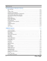
Page 5: ...fety Signs and Labels Index of Warning Placards and Decals General Safety Precautions Boating Courses Basic Seamanship Meeting Situations Visual Obstructions Boating Regulations and Requirements U S C...

Page 6: ...ttles Engine Power Trim Engine Instruments Selectable Exhaust Engine Compartment Blower Trim Tabs Theory of Operation Trim Tab Hydraulic System 3 2 3 4 3 5 3 5 3 7 3 7 3 9 3 9 3 9 3 10 3 11 3 13 3 13...

Page 7: ...erse Polarity Connecting and Disconnecting Shore Power Salon Main Circuit Breaker Panel Troubleshooting the AC System AC Wiring Codes Generator Generator Cooling System Generator Operation Generator S...

Page 8: ...ge Spring Commissioning Winterize Kohler Generator Mercruiser Air Activated Single Point Drain System Mercruiser Manual Three Point Drain System Volvo Catalytic with Joy Stick Volvo Closed Cooling Vol...

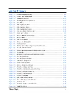
Page 9: ...inguisher Figure 3 6 Garboard Drain Figure 3 7 Battery Switch Panel Bilge Pump Circuit Breakers Figure 3 8 Fuel Tank Fill Deck Plate Figure 3 9 Fuel Tank Connections with Manual Shutoff Valves Figure...

Page 10: ...uit Breaker Panel DC Section Figure 3 37 Kohler Generator Figure 3 38 Compass Figure 3 39 Electrical Panel Figure 3 40 Coffee Maker Figure 3 41 Cook Top Figure 3 42 Galley Stove Figure 3 43 Galley Sin...

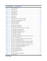
Page 11: ...Conditioning Cooling Water Pump Figure 3 80 Air Conditioning Cooling Water Pick Up Figure 3 81 Air Conditioning Cooling Water Seacock Figure 3 82 Air Conditioning Control Panel Figure 3 83 Air Condit...

Page 12: ...Plug Figure 4 9 Manual Air Pump Figure 4 10 Manual Air Pump Installed Figure 4 11 Mercruiser Blue Drain Plug Location Figure 4 12 Mercruiser Blue Drain Plug Location Figure 4 13 Mercruiser Distributio...

Page 13: ...s Table 2 8 Minimum Portable Fire Extinguishers Required Table 3 1 Switch Identification Icons Table 3 2 Water System Troubleshooting Chart Table 3 3 Battery Specifications Table 3 4 Engine and Batter...

Page 14: ...tion to craftsmanship and quality totally differentiates its boats from others and represents the company s enduring devotion to its proud past America s best naval architects designers boat builders...

Page 15: ...change without notice The data con tained herein is subservient to the manufacturers manuals of the numerous components installed in this vessel If a discrepancy exists between this manual and the com...

Page 16: ...ect to change without notice Chris Craft reserves the right to discontinue any model and make changes at any time in colors equipment specifications materials and prices Chris Craft is not obligated t...

Page 17: ...16 000 lbs 7 258 kg Deadrise 20 degrees Draft 31 78 7 cm Fuel Capacity 270 gallons 1 022 Liters Water Capacity 50 gallons 189 Liters Model Table 1 2 Maximum Person Capacities 36 RH Corsair U S Standa...

Page 18: ...wing table to approximate the weights and liquids carried aboard the boat 1 gallon of gasoline 6 1 pounds 1 gallon of 2 diesel fuel 7 05 pounds 1 gallon potable Water 8 33 pounds 1 pound 0 4536 kilogr...

Page 19: ...Introduction 36 RH Corsair B...

Page 20: ...YLEM Flow Controls 100 Cummings Center Drive Suite 535 N Beverly MA 01915 Phone 978 282 5262 Fax 978 281 4320 www rule induistries com BILGE PUMPS Introduction Ameritex Fabric Systems Taylor Made Grou...

Page 21: ...REFRIGERATOR COOLING UNIT Mercury Marine W6250 W Pioneer Road P O Box 1939 Fond du Lac WI 54936 1939 Phone 920 929 5040 Fax 920 929 5893 www mercurymarine com THROTTLE SHIFT CONTROLS CABLES Mercury Ma...

Page 22: ...r manner when encountering limited visibility rough water and other weather or people induced factors Understanding how to administer first aid including CPR Know how to treat hypothermia Be ready for...

Page 23: ...Safety and Operations...

Page 24: ...ical or Hot Water Hazard The symbol represents a hazard to skin The appropriate type of gloves shall be worn to protect skin Eye Protection The symbol of a person wearing goggles indicates that the ma...

Page 25: ...esel Fuel And Gasoline Labels Figure 2 1k Carbon Monoxide Warning Figure 2 1L Leaking Fuel Warning Figure 2 1m Carbon Monoxide Warning Figure 2 1n Discharge Of Oil Prohibited Figure 2 1o Yacht Certifi...

Page 26: ...Figure 2 1g Figure 2 1f Figure 2 1c Figure 2 1b Figure 2 1a Figure 2 1e Figure 2 1d Figure 2 1 Safety and Operations Figure 2 1h 2 5...

Page 27: ...warn ings indicate a condition that if not followed may result in injury and or damage to the boat If a warning placard label becomes unreadable Federal Law dictates that it must be replaced with a n...

Page 28: ...Safety and Operations Figure 2 1n Discharge Of Oil Prohibited Figure 2 1o Yacht Certification Figure 2 1p Illegal To Dump Figure 2 1q Warning Before Starting Figure 2 1r Fire Extinguisher 2 7...

Page 29: ...gerator Figure 2 1x Shut Off Motor Figure 2 1v GFCI Warning Figure 2 1t Boat Covers Figure 2 1u Engine Room Fire Figure 2 1s Gasoline Vapors Safety and Operations Figure 2 1y NMMA Certified Figure 2 1...

Page 30: ...is Craft before operating the vessel Read and understand this manual and various manufacturers manuals accompanying this manual If you have any questions regarding your Chris Craft or the factory inst...

Page 31: ...see and or smell can kill you Understand all the safety precautions associated with mechanical maintenance Know the limits Understand your own limits Understand the limits of your boat Don t overload...

Page 32: ...way over more agile vessels In general a power driven vessel must give way to the following A sailing vessel under sail only engines not running When the sailboat is under engine power it is considere...

Page 33: ...lose to and a risk of collision exists the vessel on the right is the stand on vessel and must hold course and speed The give way vessel must maneuver in such a way as to keep clear of the stand on ve...

Page 34: ...ngles and the sea state Other factors that can affect operator vision include but may not be limited to Acceleration Obstruction in Field of Vision Darkness Propulsion Engine Trim Angles Fog Rain and...

Page 35: ...ons to the following address for information regarding Information on boating safety recalls To comment on U S C G boarding procedures For answers to boating safety questions and for boating safety li...

Page 36: ...ed speed limit Safety and Operations Alcohol and Drugs Operating your Chris Craft under the influence of alcohol and or drugs may cause serious injury Do not drink alcohol and or take drugs and operat...

Page 37: ...ce As the owner operator you are responsible for keeping your vessel in a safe operating condition Regularly scheduled maintenance is mandatory for this to occur Load Capacity Loading and capacity ref...

Page 38: ...edures and or requirements for the country of registration as regulations and responsibilities may changed from country to country A complete list of required equipment Federal rules and regulations a...

Page 39: ...d activities While operating personal watercraft PWC During white water boating activities While sail boarding under Federal law sail boards are not boats Laws governing the use of a particular type o...

Page 40: ...r water sports Most comfortable for continuous wear Some Type III s will inflate when you enter the water IV Throwable Devices Cushion horseshoe or ring buoy style Designed to be thrown to some one in...

Page 41: ...latable Safety and Operations Table 2 3 PFD Minimum Buoyancy Requirements Foam Wearable Size Type Inherent Buoyancy Foam Adult Youth Child and Infant Throwable Cushion Ring Buoy The throwable PFD is o...

Page 42: ...er Practice using the PFD in the water This will provide insight and confidence in its use Teach all children how to put on and wear the PFD PFD Care Do not store in plastic bags locked in a compartme...

Page 43: ...mp Binoculars Spare Fuel Boat hook Sunglasses Emergency Position Indicating Radio beacon EPIRB Throwable device Extra clothing Tool kit First Aid Kit VHF Radio Flashlights Visual Distress Signals Food...

Page 44: ...ccessible where they can be reach quickly regard less of the operating conditions Disposal Pyrotechnics are valid for 42 months from date of manufacture Each pyrotechnic has a date stamp indi cating i...

Page 45: ...of the major medical emergencies you could encounter consist of but are not limited to Drowning Near drowning Hypothermia Carbon Monoxide poisoning Trauma from falling Some of the minor emergencies y...

Page 46: ...mited to Engines Generators Barbecues Portable space heaters Dizziness Weakness Irritated eyes Ears ringing Headaches Nausea Unconsciousness Carbon Monoxide is an odorless colorless tasteless gas Carb...

Page 47: ...or station wagon effect occurs Your vessel is situated next to and receives exhaust from the neighboring vessel Your vessel is slow idling or stopped Carbon Monoxide is colorless odorless and tastele...

Page 48: ...to the victim Making contact with the victim Getting the victim back aboard the vessel If an individual falls overboard it is imperative to locate and return to the victim If at night use all availabl...

Page 49: ...r Help the individual back into the vessel It is very difficult to pull a victim back into the boat via the sides The most effective recovery is at the swim platform located at the stern If the person...

Page 50: ...A Wood paper textiles trash and other ordinary combustibles Class B Flammable liquids oils solvents paints grease fuels etc Class C Electrical energized electrical equipment Class D Combustible metals...

Page 51: ...Fire Extinguishers Required Fire Extinguisher Maintenance and Service The boat owner operator shall Have fire fighting equipment checked at the intervals indicated on the equipment Replace portable f...

Page 52: ...degrees F and is entirely dependent on the intensity of the fire Signs of actuation 1 A loud sound similar to small arms fire 2 A loud sound of rushing air 3 An extinguished indicator lamp 4 A stalle...

Page 53: ...riate and acquaint yourself with new technologies that can help you navigate your vessel safely If you find yourself in unfamiliar waters and without knowledge of the hazards proceed slowly and post a...

Page 54: ...clear of debris Do not start the engines if intakes are plugged If you encounter shallow water and run aground 1 Immediately place the transmissions in neutral 2 Ensure everyone has and is wearing a...

Page 55: ...y with it 2 Climb onto the overturned hull to remove you and your passengers from the water This helps you retain body heat and reduces the possibility of hypothermia 3 Signal for help with an appropr...

Page 56: ...rm the minimum precautions that shall be applied are All occupants shall remain inside the boat Occupants shall not enter the water Arms and legs shall not dangle in the water Occupants shall refrain...

Page 57: ...2 36 Safety and Operations...

Page 58: ...rags properly 3 If appropriate open any hatches ports doors and windows to ventilate the cabin 4 Investigate for leaks and drips Make any corrections necessary The fuel deck plate cap is fitted with a...

Page 59: ...e for the component manuals that accompany your boat At the time of this writing the information contained in this chapter is current and up to date However specifications are subject to change withou...

Page 60: ...Switch Identification There are numerous switches you should be aware of when operating your boat This section identifies these switches by their icon Table 3 1 Switch Identification Icons 3 2 Systems...

Page 61: ...LIGHTS 5 AMPS BLOWERS PORT STBD 10 AMPS COURTESY LIGHTS 5 AMPS MANUAL BILGE PUMP FWD MID AFT 15 AMPS DIMMER 3 AMPS HELM SEAT OPTION 15 AMPS NAVIGATION ANCHOR LIGHT 10 AMPS TABLE LIFT 10 AMPS BIMINI LI...

Page 62: ...mp Fuel Valves Bilge Pump s Waste Tank Outdrive Other components may be included within the engine compartment depending upon options chosen The engine compartment is accessed via the engine hatch Fig...

Page 63: ...t and Convenience Equipment Safety System Never restart the engine should a fire occur Correct the malfunction that caused the fire and replace the fire bottle before you use the boat again The safety...

Page 64: ...e correct pressure If the pressure is below specification have the unit serviced You should also weigh the cylinder less the bracket for proper weight If the gross weight has deviated from the specifi...

Page 65: ...ached to the seacock protects the system from foreign objects that may enter the seacock The strainer should be periodically cleaned and inspected for effective operation Drain Plugs Ensure you re ins...

Page 66: ...ed on the Battery Switch Panel Placing these breakers to the OFF position or if they trip to the OFF position de energizes the pump The bilge pump is normally held in place with clips for easy removal...

Page 67: ...red If the pump does not start reset the circuit breakers If the pump still fails to start replace the float switch before using the boat If you have to remove the float switch verify proper operation...

Page 68: ...s Fuel Tank and Routing Lines Fuel Gauges Sending Units Fuel Shut off Valves Fill Deck Plate Fuel Tank Vents Fuel Filters Fuel Fill Hose Fuel Tank Vent Hose Engine Fuel Feed Hose Charcoal Vent Caniste...

Page 69: ...aluminum fuel tanks with capacity of 270 gallons 1 022 Liters Usable fuel will be less than capacity rating and depends upon trim conditions Good seamanship calls for an adequate fuel reserve in all b...

Page 70: ...tank feeds the starboard engine Both fuel tanks supply fuel to the generator in gasoline and diesel engine installations The return lines when used will route unburned fuel back to their respective fu...

Page 71: ...assembly itself eliminating the need of a rudder A power steering system sometimes including the Volvo Joystick and Mercury Axius System is used to make operating the boat easier A steering system own...

Page 72: ...ents associated with each engine which are discussed in this section Ignition Switches There is one ignition switch for each engine The switches are located on the helm control panel See Figure 3 11 D...

Page 73: ...top the engines 1 Turn the ignition switches to OFF 2 Turn off any circuit breakers necessary to prevent a restart 3 If required turn off the fuel shut off valve on the fuel tank Do not approach the p...

Page 74: ...e boat may be trailered or un trailered without damaging the sterndrive propeller When using the engine trim keep the following in mind Avoid a bow down condition This is known as plowing which can re...

Page 75: ...ng correct operating temperature Engine coolant temperature is not affected by seawater temperature Correct operating coolant temperature indications for your engine may be found in the engine manufac...

Page 76: ...t which provides a throaty sound when operating away from shore and a muffled exhaust when operating within basin sound limitation boundaries The mode is selected by a switch located on the helm contr...

Page 77: ...boat is equipped with an engine compartment exhaust blower which can be used to ventilate the compartment Run the blower for at least four 4 minutes to ventilate the compartment before starting the e...

Page 78: ...mage to the trim tabs may result otherwise Hydraulic Trim tabs Figure 3 17 help adjust the vessel trim for weather cross winds and water current conditions In addition they are used to adjust for list...

Page 79: ...or good performance Do not reduce the running angle less than 2 Do not use the trim tabs when backing or running an inlet Damage to the cylinders and tabs may result Fully retract the trim tabs when t...

Page 80: ...you must lower the trim tab on the listed lower side by pushing the top half of the rocker switch in a half second burst until the boat is righted If the stern of the boat is highly loaded use both s...

Page 81: ...ed the pump im mediately pressurizes the water system When the operating pressure is reached the pump shuts off until it senses a loss of pressure such as a faucet being opened at which time it is aut...

Page 82: ...3 24 Systems Figure 3 22 Fresh Water Pump and Filter Figure 3 23 Fresh Water Pressure Pump Circuit Breaker A switch Figure 3 23 on the salon circuit breaker panel energizes the pump...

Page 83: ...n each model There is an Owner s Manual that comes in your documentation package that addresses the use maintenance and troubleshooting of the system It is your responsibility to become familiar with...

Page 84: ...ted bleach per gallon of fresh water 4 Dump water into water tank Fill the remainder of the tank with fresh water 5 Activate the water pump and allow air to bleed from the system Ensure the sanitizing...

Page 85: ...use the fresh water system 1 Sanitize the system as previously described 2 Fill the water tank with potable water 3 Energize the pressure pump a The boat must have electrical power to energize the pr...

Page 86: ...Seacock strainer is clogged Water tank is empty Air in system Pump breaker OFF Water tank is empty Blocked water lines Defective pump pressure switch Pump breaker OFF Water tank is empty Defective pu...

Page 87: ...package addresses the use maintenance and troubleshooting of the Techma waste system It is your responsibility to become familiar with its contents as only rudimentary information is presented here Th...

Page 88: ...Figure 3 26 Fluid Tank Sensor 3 30 Systems...

Page 89: ...nded with the electrical system energized except automatic bilge pumps fire protection and alarm circuits Allow the shore power cable to hang in the water An electrical field may be caused which can c...

Page 90: ...the DC systems Each master red switch engages or disengages a specific battery The small breaker switches energizes and protects specific circuits and components attached to this panel Some components...

Page 91: ...ation about this panel is provided in Salon Main Circuit Breaker Panel on page 3 44 Figure 3 29 Zinc Plate Zinc Plate Both the AC and DC systems must be grounded in order to function properly The 36 R...

Page 92: ...enerator House The Generator battery is also known as the House battery which supplies power to several DC systems of the boat Explosive hydrogen gas is given off by charging batteries Batteries will...

Page 93: ...Cables are color coded Blue Blue Tape On Yellow Cable is the Ground for the House Battery Blue Blue Tape On Red Cable is the Positive for the House Battery Red Red Tape On Yellow Cable is the Ground...

Page 94: ...The charger is protected by three circuit breakers on the Battery Switch Panel The three breakers control which battery is charged port battery starboard battery or generator house battery By default...

Page 95: ...is turned ON Ships Service Helm Service Electronics Service The following systems are engaged when the Starboard Engine Red Master Battery Switch is turned ON Engine Hatch Windlass Each of these syst...

Page 96: ...h Some of these colors can serve more than one type of circuit Table 3 4 illustrates the color codes for the engine compartment and battery wiring Table 3 4 Engine Battery Wire Codes FUNCTION WIRE COL...

Page 97: ...P WHITE RED GENERATOR POWER RED VIOLET GENERATOR PRE HEAT WHITE GENERATOR START YELLOW RED PORT PARALLEL START RED STARBOARD PARALLEL START RED BOW THRUSTER POWER RED BOW THRUSTER BATTERY RED BOW THRU...

Page 98: ...Engine alternator belt loose Bad battery Turn switch ON SOLUTION Tighten belt Replace battery Battery selector switch turned to OFF Battery disconnect switch to OFF Switch selector switch ON for Port...

Page 99: ...ows for connection of the shore power cords Actual location of the cords and plug ins is on the Port Aft transom Work with your dealer for the proper connection of the shore power cords for the 36 RH...

Page 100: ...urrent carrying conductor and the grounded current carrying conductor The shore panel automatically senses a reverse polarity and turns on a Reverse Polarity Light Never ignore a reverse polarity indi...

Page 101: ...t receptacles and lock in place For safety reasons do not attach the power cord to the dock first 3 Plug in the cord at the dock station Turn on dock station breakers 4 Turn ON shore power control bre...

Page 102: ...er 1 and or Shore Power 2 switch ON When power is available the green light above the switches illuminates 4 Read the power input on the volt meters located on the panel Select Line 1 or Line 2 to rea...

Page 103: ...Salon Main Circuit Breaker Panel Figure 3 32 controls the DC power system This section receives it power feed from the Generator House battery The red master Generator battery switch must be turned O...

Page 104: ...rying grounding and bonding conductors There are several additional basic colors and color combinations for different circuits used beyond the ignition switch Some of these colors can serve more than...

Page 105: ...in the engine compartment and accessed via the engine hatch AFT Figure 3 37 Kohler Generator AC Color Codes 3 47 Systems Generator For domestic delivery there are four different types of generators th...

Page 106: ...located on the Salon Main Circuit Breaker Panel Local start and run switches are different between a gas driven generator and a diesel driven generator thus it is im portant to read and understand the...

Page 107: ...on of this switch is CLOSED When depressed it opens the DC circuit of the control panel and shuts down the generator Since this switch is not spring loaded it can be used to keep the generator off whe...

Page 108: ...rom the generator Allow it to run for another three to five minutes to stabilize the operating temperature 2 Depress and hold the Stop switch until the generator comes to a complete stop Release the S...

Page 109: ...switch to the down Stop position and hold momentarily 2 Release the switch when the generator stops Compass A compass is installed on each boat to aid in navigation A magnetic compass is often deflect...

Page 110: ...rner cooktop refrigerator trash receptacle and storage compartments Most of the components in the galley require AC power to operate but the galley refrigerator can be operated on either AC or DC powe...

Page 111: ...r Figure 3 45 Trash Receptacle 3 53 Systems 6 7 7 These numbers describe the items located in the galley See pages 3 52 and 3 53 1 Electrical Panels 2 Microwave Oven 3 Coffee Maker 4 Cooktop Stove 5 G...

Page 112: ...t is an instruction manual that details the proper use and care of the system The cockpit refrigeration system Page 3 55 consists of a 12VDC cold plate with adjustable thermostat When operation on the...

Page 113: ...Entertainment and Convenience 3 55 Systems Figure 3 48 Cockpit Refrigerator Figure 3 47 Wet Bar and Sink...

Page 114: ...on the Battery Switch Panel The Starboard Engine Red Master Switch must be energized for the system to operate The windlass compartment located at the bow contains a fresh water wash down allowing you...

Page 115: ...Care and Cleaning 3 57 Systems Marine Tops And Covers Care And Cleaning...

Page 116: ...Care and Cleaning Figure 3 51 Canvas Top 3 58 Systems...

Page 117: ...Care and Cleaning 3 59 Systems Cleaning and Maintenance of Teak Things You Will Need Teak or Tung Oil Sponge Soap Flakes Teak Cleaner Sandpaper Fresh Water Hose Rags Paint Brush...

Page 118: ...Care and Cleaning 3 60 Systems Maintenance and Cleaning Of Stainless Steel...

Page 119: ...and provide a gentle push that you will control away from or to the dock or seawall If you have not experienced using a bow thruster it is recommended that you are checked out by the dealer on how to...

Page 120: ...d a clean cloth Dry the eisenglass with a clean absorbent cloth or towel to prevent water spots Now the windows are ready for a UV protectant and or polish DO NOT Do not use window cleaner Windex dete...

Page 121: ...3 63 Systems Grey Water Systems Figure 3 56...

Page 122: ...qual 15 mm 4 2 Adapter Straight 15 mm Elbow Stem 15 mm 9 1 Elbow Adapter 1 2 BSP Nipple 3 4 1 2 Adapter Female 1 2 BSP Strainer Water Shurflo 1 Tee Stem WX1521B 2 2 Adapter Stem NRV 1 2 MPT Washdown F...

Page 123: ...Pressurized Blue Water Tubing Non Pressurized DESCRIPTION 3 2 3 2 1 1 1 X X X X QTY 1 2 3 4 5 6 7 8 9 10 11 ITEM Sanitation System Vent Filter Sanitation System Dockside Discharge Vacuum Generator In...

Page 124: ...acock is clearly marked and accessible 3 66 Systems Figure 3 59 Figure 3 60 Figure 3 61 Figure 3 62 Figure 3 59 Figure 3 60 Figure 3 61 Figure 3 62 OVERBOARD DISCHARGE OPERATION OPERATE IN ALLOWED ARE...

Page 125: ...r the installation must be of a marine grade type stainless steel or equivalent and monitored annually to ensure the lights remain in service for years to come Always test the lights BEFORE the boat g...

Page 126: ...Figure 3 70 Figure 3 68 3 68 Systems Figure 3 66 Figure 3 67 Figure 3 69 Cockpit Table...

Page 127: ...attery it will be possible to open the engine hatch by attaching jumper cables to the battery posts located directly below the helm seat NEVER REVERSE THE POLARITY ON THE BATTERY POSTS SEVERE DAMAGE W...

Page 128: ...et in the head is GFI protected because it draws it s power from the GFI outlet at the helm station Figure 3 76 Figure 3 77 3 70 Systems GFI Outlets Figure 3 75 Figure 3 73 Helm Station GFI Outlet Hel...

Page 129: ...ply hose to sea strainer AC seawater strainer Air conditioning seawater inlet hose Cooling seawater hose to AC unit AC pump Cooling Water Outlet Thru Hull Fitting Cooling Water Outlet Hose Figure 3 79...

Page 130: ...located in the important papers pouch The cabin air conditioner is 16 BTU The cockpit air conditioner is 12 BTU Air Conditioner Seawater Pumps Strainers Air Conditioning Seawater Inlet Hoses Cooling...

Page 131: ...Figure 3 91 Figure 3 90 3 73 Systems Hard Top Air Conditioning Units 2 Each Cooling Water Outlet Thru Hull Fittings Condensation Sump Pump Figure 3 92...

Page 132: ...m Switch Panel Figure 3 96 SUN ROOF SUN SHADE DO NOT USE THE SUN SHADE FOR A HAND HOLD THIS COULD LEAD TO PERSONAL INJURY AND DAMAGE TO THE SHADE DO NOT RUN THE BOAT ABOVE IDLE SPEED WHEN THE SUN SHAD...

Page 133: ...the hatch when closing the roof The sliding hatch is not designed as a walking sur face The 36 Corsair hard top is not intended to be used as a platform to sit on stand on or walk on When necessary t...

Page 134: ...3 76...

Page 135: ...ng all water from the boat that might otherwise freeze and damage plumbing and components In those areas where water cannot be removed anti freeze is added to prevent freezing and damage The procedure...

Page 136: ..._______ Inspect the boat regularly during storage Fresh Water Systems _______Turn on the pressure water pump open all faucets and drain the system completely Leave all faucets open Ensure the storage...

Page 137: ...ace anchor lines and gear Fuel System _______ Thoroughly check each fitting and hose in the fuel system Ensure it is fuel and vapor tight _______ Open any valves closed for winterization Engines _____...

Page 138: ...orage and Commissioning 4 4 Kohler Generator Generator Sea Strainer Drain Plug Figure 4 1 Warning Do not drain anti freeze from the closed cooling system drain plugs Muffler Drain Plug Generator Seaco...

Page 139: ...t or until depleting the coolant mixture Replace lead 87 7 Remove the drain plug in the generator sea strainer and completely drain the water 8 Place the plug in the important papers bag 9 Remove the...

Page 140: ...ds 9 Allow the system to drain for a minimum of five 5 minutes 10 Add air as necessary to keep the green indicators extended 11 Crank the engine over with the starter motor to purge any water trapped...

Page 141: ...er pump located on the lower starboard side of the engine 5 Verify that water is draining from each opening Allow the system to drain for a minimum of five 5 minutes 6 Place plugs in the important pap...

Page 142: ...cate and remove the water pump hoses at the front of the engine and allow water to drain completely out 6 Place four 4 drain fittings two 2 hose clamp garboard drain 7 For closed cooled engines FWC lo...

Page 143: ...es 5 Note the hose orientation of the raw water pump Loosen the hose clamps and remove the hoses from the raw water pump 6 Crank the engine briefly one or two crankshaft revolutions but do not start t...

Page 144: ...Winterization Closed Cooling Drain And Winterization 4 10 Warning Do not drain anti freeze from the closed cooling system drain plugs Note Ensure that the petcock 3 is closed before starting the engi...

Page 145: ...and a clean cloth Dry the eisenglass with a clean absorbent cloth or towel to prevent water spots Now the windows are ready for a UV protectant and or polish DO NOT Do not use window cleaner Windex de...

Page 146: ...r etc Explain exactly what the problem cause is and ask what action will be taken to resolve it The Department Manager may find it necessary to contact Chris Craft on behalf of the customer in order t...

Page 147: ...that offered by the manufacturer of the product or its authorized representative in the specific county and should be addressed by them Power train Manufacturers used by Chris Craft for this boat is...

Page 148: ...dent Report APPENDIX B Coast Guard Accident Report This appendix contains a copy of the Coast Guard Accident Report currently in use If you are involved in an accident ensure you verify that you are u...

Page 149: ...Coast Guard Accident Report B 2 Appendix B...

Page 150: ...Coast Guard Accident Report B 3 Appendix B...

Page 151: ...B 4 Appendix B Coast Guard Accident Report...

Page 152: ...Coast Guard Accident Report B 5 Appendix B...

Page 153: ...nerary vessel description expected date of arrival at your destination and your expected return time Leave the plan with a friend or rela tive who in turn can notify the Coast Guard in the event you f...

Page 154: ...C 2 Appendix C SPECIAL NOTICE TO MARINERS Float Plan...

Page 155: ...Appendix C C 3 Float Plan...

Page 156: ...ecautions 9 All skiers must wear a USCG approved personal flotation device PFD 10 Ensure everyone understands the hand signals 11 A competent observer must watch the skier at all times and keep the dr...

Page 157: ...re illustrated below Left Turn Arm outstretched pointing left Right Turn Arm outstretched pointing right Skier OK Hands clenched to gether overhead Speed OK Raised arm with thumb and finger joined to...

Page 158: ...Navigational Aids D 3 Appendix D...

Page 159: ...Lateral Aids D 4 Appendix D...

Page 160: ...use this specific log to document maintenance actions as you may have a preference for a certain style of maintenance log available on the open market It is however impor tant that you keep some type...

Page 161: ...Maintenance Log Forms E 2 Appendix E...

Page 162: ...Maintenance Log Forms E 3 Appendix E...

Page 163: ...Glossary Of Boating Terminology Appendix F F 1...

Page 164: ...F 2...

Page 165: ...F 3...

Page 166: ...F 4...

Page 167: ...F 5...

Page 168: ...F 6...

Page 169: ...5 7 F 7...

Page 170: ...F 8...

Page 171: ...F 8...

Page 172: ...G 1 Figure 4 21...

Page 173: ...G 2 Figure 4 22...

Page 174: ...G 3 Figure 4 23...

Page 175: ...G 4 Figure 4 24...

Page 176: ...G 5...

Page 177: ...G 6 Figure 4 26...

Page 178: ...G 7 Figure 4 27...

Page 179: ...G 8 Figure 4 28...

Page 180: ...Figure 4 29 G 9...

Reviews: