3-37
Systems
Battery Powered Systems
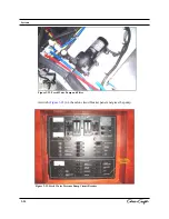
The Battery Switch Panel controls how battery power is distributed. Some DC systems are constantly
powered while others require the Red Master Battery Switches (Port Engine, Starboard Engine,
Generator / House) be turned
ON.
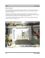
It is important to keep the battery charger working (connected to
shore power) when the craft is not in use, otherwise the batteries may discharge due to the stereo memory
and the carbon monoxide monitors.
The following systems are under constant power regardless of the Red Master Switch setting:
• Bilge Pumps
• Audio/Video Memory
• CO Monitors
• Shower Sump
The following systems are engaged when the Generator/House Red Master Battery Switch is turned
ON:
• Ships Service
• Helm Service
• Electronics Service
The following systems are engaged when the Starboard Engine Red Master Battery Switch is turned
ON:
•
Engine Hatch
• Windlass
Each of these systems may be disengaged by turning the appropriate battery switch to
OFF.
A DC powered fuse block is also installed on the boat. This fuse block is located in the cabin on the
starboard side. This fuse block permits the owner to install additional and/or aftermarket components to
the boat. To power the fuse block the Generator/House battery must be energized and the Electronics
Service circuit breaker on the Battery Switch Panel turned
ON.
Battery Specifications
Table 3-3
provides an overview of the batteries cranking power.
Table 3-3. Battery Specifications
Battery
Starboard
Port
Group
27
27
CCA
800
800
Reserve
Minutes
180
180
Volts
12 Volts
12 Volts
Generator/House
27
600
160
12 Volts
Summary of Contents for 2014 36 RH Corsair
Page 19: ...Introduction 36 RH Corsair B...
Page 23: ...Safety and Operations...
Page 57: ...2 36 Safety and Operations...
Page 88: ...Figure 3 26 Fluid Tank Sensor 3 30 Systems...
Page 115: ...Care and Cleaning 3 57 Systems Marine Tops And Covers Care And Cleaning...
Page 116: ...Care and Cleaning Figure 3 51 Canvas Top 3 58 Systems...
Page 118: ...Care and Cleaning 3 60 Systems Maintenance and Cleaning Of Stainless Steel...
Page 121: ...3 63 Systems Grey Water Systems Figure 3 56...
Page 126: ...Figure 3 70 Figure 3 68 3 68 Systems Figure 3 66 Figure 3 67 Figure 3 69 Cockpit Table...
Page 134: ...3 76...
Page 149: ...Coast Guard Accident Report B 2 Appendix B...
Page 150: ...Coast Guard Accident Report B 3 Appendix B...
Page 151: ...B 4 Appendix B Coast Guard Accident Report...
Page 152: ...Coast Guard Accident Report B 5 Appendix B...
Page 154: ...C 2 Appendix C SPECIAL NOTICE TO MARINERS Float Plan...
Page 155: ...Appendix C C 3 Float Plan...
Page 158: ...Navigational Aids D 3 Appendix D...
Page 159: ...Lateral Aids D 4 Appendix D...
Page 161: ...Maintenance Log Forms E 2 Appendix E...
Page 162: ...Maintenance Log Forms E 3 Appendix E...
Page 163: ...Glossary Of Boating Terminology Appendix F F 1...
Page 164: ...F 2...
Page 165: ...F 3...
Page 166: ...F 4...
Page 167: ...F 5...
Page 168: ...F 6...
Page 169: ...5 7 F 7...
Page 170: ...F 8...
Page 171: ...F 8...
Page 172: ...G 1 Figure 4 21...
Page 173: ...G 2 Figure 4 22...
Page 174: ...G 3 Figure 4 23...
Page 175: ...G 4 Figure 4 24...
Page 176: ...G 5...
Page 177: ...G 6 Figure 4 26...
Page 178: ...G 7 Figure 4 27...
Page 179: ...G 8 Figure 4 28...
Page 180: ...Figure 4 29 G 9...

