background image

Stacking Frame Installation Instructions 


013-100342-01 (Rev.1) (08/06) 

10 of 12 pages  


Projector Alignment 


Ensure the stacking legs are extended at least 1” and are slightly loose before 
aligning the projectors. 


Stacked projectors must be correctly aligned to one another so the resulting display is 
optimized and as sharp as possible. If hoisting the stack do so first and then align. To 
maintain alignment lock all stacking hardware into place. 

• 

Always align the 

fixed

 projector. For floor or table-mount (i.e. non-hoisted) stacks, 

align the bottom projector. In hoisted stacks, align the top projector. 

• 

Leg nuts must be loosened before alignment; otherwise the stacking mounts will 
not turn and allow movement of the projector. 


1. 

Position the fixed projector’s image as desired and align the other image(s) to it. 

2. 

To distinguish between the images, enable Red for one display and Green for the 
other. For more information, refer to the manual supplied with the projector.  

3. 

Minimize each projector’s zoom until the images are focused. 


4. 

Adjust the zoom and lens offset on the top projector to precisely move its test 
pattern display onto the bottom test pattern. When it is properly aligned all the 
Red/Green grid lines in the combined image will turn Yellow. 

• 

If all lines are well-aligned, skip to Step 7 to lock all stacking mounts. 

• 

If alignment needs improvement, 
proceed to Step 5. 

5. 

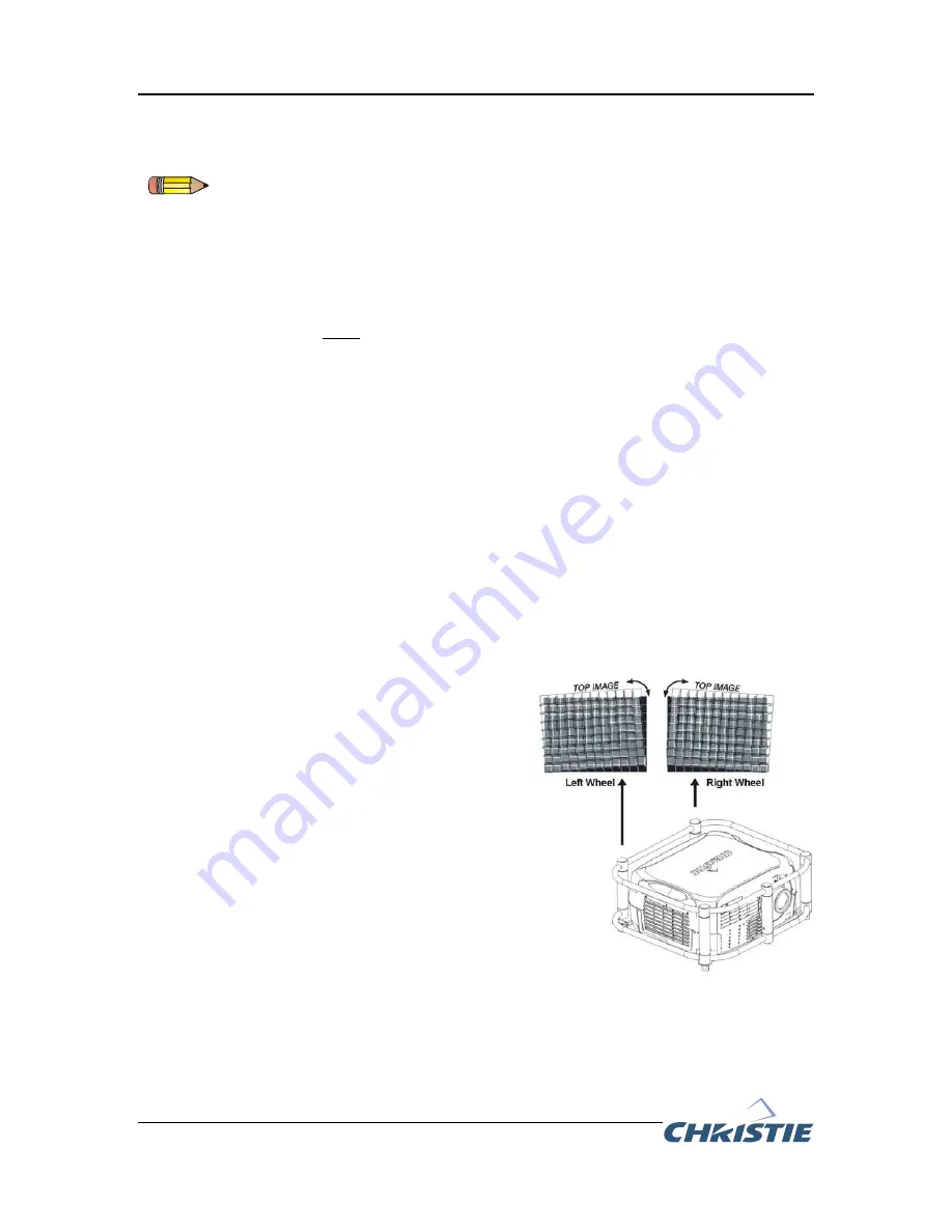
For well-aligned center lines turn the two 
rear stacking mount wheels to move the top 
projector. Use a screwdriver in the holes 
around the rim of each adjusting wheel for 
better leverage and control. Turned 
independently, each stacking mount acts as 
a pivot point for the opposite edge of the 
display. Refer to Figure 7.  For example, turn 
the right mount to tilt the left portion of the 
image and turn the left mount to tilt the right 
portion of the image. Turn the mounts 
together to raise or lower the top image, or 
turn the front stacker. If the center lines form 
an X it indicates the projectors (and 
images) are slightly tilted in relation to one 
another. Turn one mount to raise one side, 
and/or turn the other mount to lower the 
other side. Refer to Figure 7. 


Figure 7. Directional Adjustment (Tilt) 


OFFICIALLY RELEASED 

Document Control 

September 8, 2006 


Summary of Contents for 104-006101-XX

Page 1: ...e S User s Manual Table 1 Projector Models Projector Model Model Number Christie DS 4K 38 DSP104 xx Christie DS 5K Kc 38 DSP104 xx 38 DSP104 5x Christie DS 8K 38 DSP106 xx 38 DSP106 5x DLV1920 DX 104 017101 xx DLV1400 DX 38 DSP102 xx Christie DW3K Kc 38 DHD103 xx 38 DHD103 5x Christie DW6K Kc 38 DHD106 xx 38 DHD106 5x Christie HD5K 104 006101 xx Christie HD5Kc 104 007101 xx Christie HD8K 104 00810...

Page 2: ...arry a stack of projectors Always follow the Hoisting Procedure outlined on page 6 Use metric hardware only Never force incompatible threads Always use all rigging points The stacking frame handles have a maximum load capacity of 360 lbs The projectors can be stacked and hoisted in either an upright or inverted position Do not mix orientations in a stack i e inverted and upright All rigging must b...

Page 3: ...e AC power cord after the cooling fans have stopped Allow the projector to cool for at least 45 minutes 2 Place the projector into the stacking frame so the cut outs in the bottom mounting plate of the frame align with the fold mirror and adjustable feet access points on the projector Refer to Figure 2 3 Use a 10mm socket wrench to tighten the six 6 M10 bolts securing the mounting plate to the bot...

Page 4: ...a secure table or cart For upright stack Place the projector to be positioned on the bottom of the stack on the table or cart Ensure the adjustable feet are NOT retracted on the bottom projector When installing the second and third projector in the stack the feet must be retracted All projectors must be stacked in the same orientation For inverted stack Place the projector to be positioned on the ...

Page 5: ...he legs should fit inside the stacking mounts 6 Turn the adjusting wheel on each stacking mount until the hole in the top portion of the mount lines up with the hole in the stacking leg To make alignment easier insert a screwdriver into one of the holes and use it to align the two holes WARNING Step 7 is a critical safety procedure that must be observed Failure to engage the safety locks could cau...

Page 6: ...hoisting techniques available These two options are used for the various stacking combinations and for the hardware options available These options include hoisting via the stacking frame handles or hoisting via the hardware on Roadster Mirage S and Roadster HD12K models Key Points When hoisting a stack combining Roadster Mirage S and Roadster HD12K models with any of the models listed in Table 1 ...

Page 7: ...ables when hoisting and attach them to the two eyebolts on the stacking frame 2 Attach a safety cable to at least of the eyebolts mounted on the bottom of the stacking frame 3 Secure the rigging components to the appropriate rigging points Refer to the designated labels on the stacking frame handles for rigging positions 4 It is mandatory to use four rigging points Ensure the straps clamps or cabl...

Page 8: ...e hardware on the Roadster Mirage S and Roadster HD12K models to hoist the stack WARNING The four top rigging points have a maximum loading capacity of 800 lbs each When hoisting from the bottom of the projector use at least four of the eight rigging points two opposite sets Use metric hardware only M12 thread Figure 5 Hoisting via Roadster Mirage S Roadster HD12K Hardware O F F I C I A L L Y R E ...

Page 9: ... eyebolts mounted on the bottom of the projector Refer to Figure 6 3 Secure the rigging components to the appropriate rigging points Eight sliding points are provided on the bottom of the projector To prevent sliding tighten the nut at each required location 4 Use at least four rigging points two opposite sides and ensure the straps clamps or cabling meet the adequate load capacity for the total p...

Page 10: ... the zoom and lens offset on the top projector to precisely move its test pattern display onto the bottom test pattern When it is properly aligned all the Red Green grid lines in the combined image will turn Yellow If all lines are well aligned skip to Step 7 to lock all stacking mounts If alignment needs improvement proceed to Step 5 5 For well aligned center lines turn the two rear stacking moun...

Page 11: ...hen adjust focus When aligned all lines from the combined Red Green grids will be Yellow WARNING Step 7 is a critical safety procedure that must be observed Failure to properly secure the stacking wheels could cause the projectors to separate resulting in possible injury or death 7 Turn all three stacking wheels until they are firmly secure against the rest of the stacking mount 8 Secure both rear...

Page 12: ...112 CHRISTIE Digital Systems Inc Willicher Damm 129 D 41061 Mönchengladbach Germany Tel 49 2161 664540 Fax 49 2161 664546 CHRISTIE Digital Systems Inc 7 av Georges Pompidou 92593 Levallois Perret Cedex France Tel 33 0 1 47 48 28 07 Fax 33 0 1 47 48 26 06 ASIA PACIFIC OTHER CHRISTIE Digital Systems Inc 627A Aljunied Road 05 02 Biz Tech Centre Singapore 389842 Tel 65 6877 8737 Fax 65 6877 8747 CHRIS...

Reviews: