4-26
J Series 1000W and 1200W Service Manual
020-100725-04 Rev. 1 (07-2015)
Section 4: Parts and Module Replacement
4.9.7 Remove the Backplane Module (BPM)
(42 minutes)
1. Remove the top cover. See
.
2. Remove the card cage assembly. See
3. Remove the panel driver. See
4. Remove the LVPS. See
Remove the Low Voltage Power Supply (LVPS)
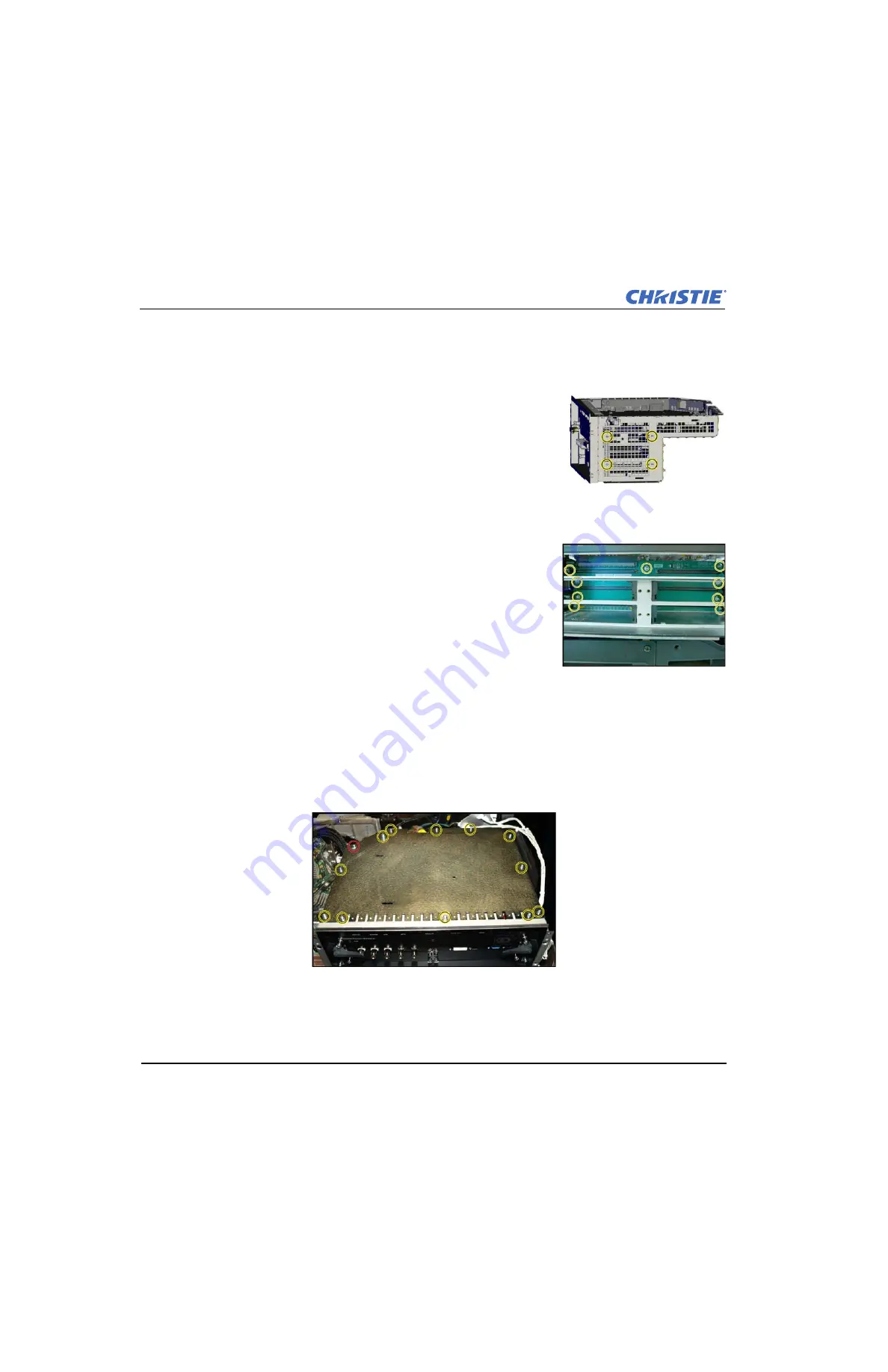
5. Remove (4) #2 Phillips® screws from the back of the card cage.
6. Remove the SIPC. See
Remove the Image Processing Card
.
7. Remove all option cards. See
8. Remove the black option card alignment trays by unsnapping them from
both sides of the card cage.
9. Remove (9) #2 Phillips® screws, which secure the backplane module.
10. Remove the backplane.
4.9.8 Remove the Panel Driver
(20 minutes)
1. Remove the top cover. See
.
2. Remove (3) 3 mm hex screws from the transparent engine duct on top of the engine cover. Remove the
engine duct.
3. Remove (1) 3 mm hex screw from the black card cage duct on the side of the card cage, as shown in red.
Remove the card cage duct.
4. Remove (12) #2 Phillips® screws from the metal lid on the top of the card cage, as shown in yellow.
Remove the lid.
5. Remove (22) harnesses that are connected to the panel driver. Remove the harnesses from the panel driver
harness clips.
NOTICE!
Make note of which harnesses are routed through which clips.
6. Remove (6) 2.5 mm hex screws, which secure the 3 light engine communication cables.
Summary of Contents for Christie DS+10K-J
Page 1: ...J Series 1000W and 1200W Service Manual 020 100725 04...
Page 56: ......
Page 58: ......
Page 72: ......
Page 76: ......


