background image

4-12

Entero RPMSP/RPMWU/RPMHD-LED01 Service Manual

020-100368-05 Rev. 1 (06-2012)

Section 4: Parts and Module Replacement

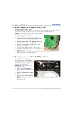
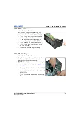
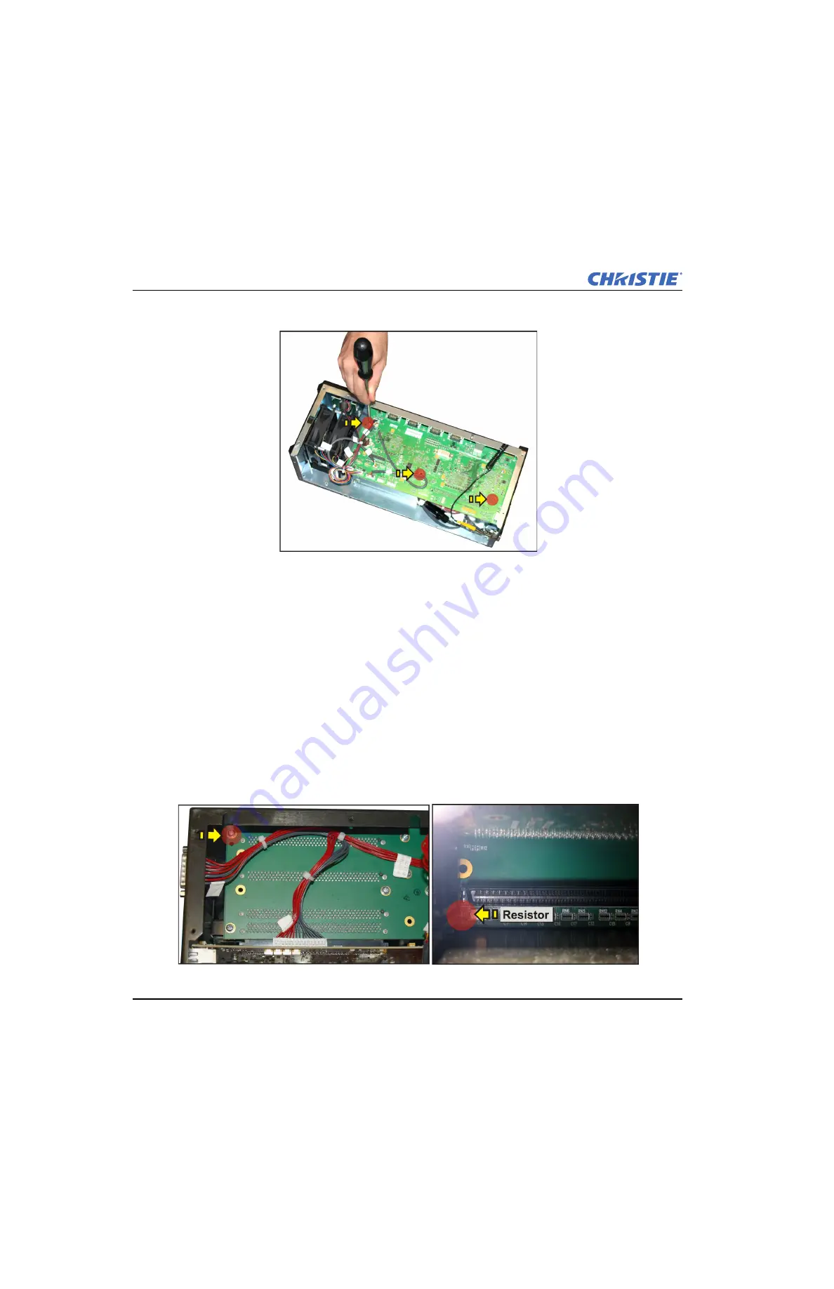
12. Remove (3) #1 Phillips® screws from the standoffs securing the QDEC to the EM frame. 

NOTE:


One of these stand-offs secures the RTSM to the board

.

13. Remove (8) #1 Phillips® screws securing the backplane module to allow the QDEC and backplane to slide 

out of the EM together.

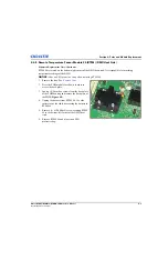
14. Disconnect the power harness from the bottom of the QDEC (from fuse 12A harness on Entero LED).
15. Unlock the plastic cable fastener attached to the center of the backplane module and remove the fuse/

breaker harness from the fastener.

16. Disconnect the QDEC from the backplane module.

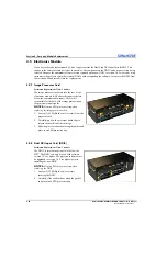
4.5.4  Passive Backplane Module

Estimated Replacement Time: 30 minutes

1. Remove the QDEC. See 

4.5.3 Quad DVI EM Controller (QDEC)

.

2. Transfer your settings to the new backplane. See 

7.2 Replace Backplane

.

3. Remove (8) #1 Phillips® screws securing the back plane module. 

NOTICE: 

When reassembling the back plane, make sure to avoid contact with the resistor located on the 

opposite side of the top-left mounting screw.

Summary of Contents for Entero RPMHD-LED01

Page 1: ...Entero RPMWU RPMSP RPMHD LED01 S E R V I C E M A N U A L 020 100368 05 ...

Page 2: ......

Page 3: ...Entero RPMWU RPMSP RPMHD LED01 S E R V I C E M A N U A L 020 100368 05 ...

Page 4: ...h high quality materials and components that can be recycled and reused This symbol means that electrical and electronic equipment at their end of life should be disposed of separately from regular waste Please dispose of the product appropriately and according to local regulations In the European Union there are separate collection systems for used electrical and electronic products Please help u...

Page 5: ...hooting Guidelines 3 1 3 4 System Warnings Errors 3 2 System Warnings 3 2 System Errors 3 2 3 4 1 LED Status Display On the Projector 3 3 3 4 2 Error Codes 3 4 3 5 Projector Does Not Power ON 3 5 3 6 Light Module Suddenly Goes OFF 3 5 3 7 Displays 3 6 3 7 1 The Projector is ON but No Display 3 6 3 7 2 The Display is Jittery or Unstable 3 6 3 7 3 The Display is Faint 3 6 3 7 4 The Upper Portion of ...

Page 6: ... 3 13 3 10 2 Troubleshooting Tree Array Brightness 3 14 3 10 3 Troubleshooting Tree Array Colors 3 15 3 10 4 Bright ColorLOC Setup Walkthrough 3 16 3 10 5 Array Status Decoder Setting The RGB Brightness Target Unit 3 17 3 11 Hardware Troubleshooting Trees 3 18 3 11 1 Troubleshooting Trees Error Codes 3 18 3 11 2 Troubleshooting Trees Error Codes Continued 3 19 3 11 3 Troubleshooting Trees Error Co...

Page 7: ...ary Settings 7 1 7 1 1 Red Green Blue and White X Y 7 2 7 1 2 Auto Color Enable 7 2 7 1 3 Color Enable 7 2 7 1 4 Reset to Factory Color Primaries 7 2 7 2 Replace Backplane 7 2 7 3 Remote Access Level 7 2 7 4 Restore Factory Defaults 7 2 7 5 Erase Data Files 7 3 7 6 Delete All Real Time Events 7 3 7 7 Status 7 3 7 8 Default Color Adjustment 7 3 7 9 Color Management 7 3 7 9 1 Native Color Settings 7...

Page 8: ...Copy From 7 8 7 9 4 Color Saturation 7 8 Red Green Blue Parts of Primary Colors 7 8 Auto Color Enable 7 8 RGB Brightness 7 8 7 10 ArrayLOC Service 7 9 7 10 1 Bright ColorLOC Mode 7 9 7 10 2 ArrayLOC Group 7 9 7 10 3 Broadcast Interval 7 9 7 10 4 Adjustment Interval 7 9 7 10 5 Duty Cycle Mode 7 9 ...

Page 9: ... accurate and complete However due to continuing research all information is subject to change without notice Christie assumes no responsibility for omissions or inaccuracies 1 1 1 Labels and Marking Observe and follow any warnings and instructions marked on the projector Danger symbols indicate a hazardous situation which if not avoided will result in death or serious injury This signal word is t...

Page 10: ... for projection onto flat front or rear projection screens The modular design of these projectors makes them an ideal choice for rear screen projection and multi display walls With built in flexibility each projector is configurable for straight throw or 90 mirrored applications The unique 6 axis adjustment mechanism enables accurate alignment of the lens to the screen minimizing distortion at all...

Page 11: ...te the part numbers of the items required See Table 4 1 Service Parts List and 2 2 Safety Warnings and Guidelines Also quote the projector model number serial number and date of manufacture NOTE Some parts identified in the service parts list may not be available separately In addition some parts stocked as inventory are available only until the current supply lasts All part numbers are subject to...

Page 12: ...ower sources to the projector before servicing or cleaning If any of the following conditions exist immediately disconnect the projector from the power outlet and consult a Christie accredited service technician The power cord is damaged The internal cooling fans do not turn ON when the projector is first powered up Liquid is spilled into the projector The projector is exposed to excessive moistur...

Page 13: ... operation To assure complete safety at all times it is imperative the following precautions be taken during servicing and the original projector design remain intact 2 2 3 AC Power Precautions Power should always be disconnected from the illumination module before servicing to avoid the possibility of inadvertent exposure to visible and invisible LED radiation Directly viewing the illumination mo...

Page 14: ...aining the cleanliness of all internal components during a service procedure is critical All of the optics must remain free of contaminants in order to perform at the level specified for the projector Even a small amount of dust or a fingerprint may degrade the image or cause a noticeable reduction of brightness During servicing take all necessary measures to avoid touching or contaminating optica...

Page 15: ...lean high quality optical cloth Light Engine components Do not touch or blow on components Wear gloves supplied Blow off particles with clean dry de ionized air If necessary use a split Q tip with pure isopropyl alcohol on the glass surface Light Engine DMD panels Do not touch or blow on the panels Blow off particles with clean dry de ionized air Projection Lens To avoid the risk of scratching the...

Page 16: ...ard Do not spill liquids into the projector If a spill occurs immediately disconnect the projector and have it serviced by a Christie accredited service technician 2 5 Replace the Light Module Do not service the projector while it is still connected There are exposed voltages that could cause severe physical injuries and possibly death Always power down and disconnect disengage all power sources t...

Page 17: ...ve a performance issue the cause need only be traced down to the module level at which point the faulty module is usually replaced No further analysis is necessary 3 2 Troubleshooting Trees This section provides troubleshooting procedures that can help direct you to the most likely cause of a specific performance problem Refer to this section if you cannot eliminate the problem through proper adju...

Page 18: ...he OSD menu system and the WebUI update automatically when the error condition is corrected The error code displayed on the projector status panel must be cleared manually by pressing Exit from the presentation level no OSD on screen If an error code recurs try resetting the projector by turning the projector OFF and ON A persistent error code may indicate that you need to contact a Christie accre...

Page 19: ...s LED STATUS 2 CHARACTER DISPLAY DESCRIPTION Solid yellow Rotating Warming up Pr Programming TI FS Fail safe mode EM in fail safe mode See the Visual Environments Projector Software Upgrade Instruction Sheet 020 100443 XX static Standby mode up and down Brief cool down period Solid green BO Booting when power first applied The projector LED will go through phases B1 Boot phase 1 starting main scri...

Page 20: ...ear the error by pressing Exit twice when at the presentation level no OSD on the screen If the error recurs then try resetting the projector by powering OFF and ON again Contact the dealer if the problem persists or if you see a code not listed in the following table Table 3 2 Error Codes ERROR CODE ITEM DESCRIPTION Light Engine LE 01 Light engine link error 02 Light engine initialization error 0...

Page 21: ...unctioning 04 PHM FD DMD overtemp or sensor not functioning 05 PHM QDPC board overtemp or sensor not functioning 06 LM Air inlet overtemp or sensor not functioning 07 LM Air exhaust over temp or sensor not functioning 08 LM Power supply overtemp or sensor not functioning 09 LM LED Driver overtemp or sensor not functioning 10 LM ambient overtemp or sensor not functioning 11 LM Red thermistor overte...

Page 22: ... The Display is Faint The source may be double terminated Make sure that the source is terminated only once The source if non video may need sync tip clamping Check RGB Brightness setting and Brightness Uniformity control If the ChristieTWIST software was used test by disabling the blend 3 7 4 The Upper Portion of the Display is Wavy Tearing or Jittery Check your source this can occur with video o...

Page 23: ...GD and or Color Space file for the source is used 3 7 11 Display is not Rectangular Check leveling of the projector Make sure the lens surface and screen are parallel to one another Make any necessary adjustments to the vertical offset on the lens mount Check geometry corrections settings for example keystone adjustment 3 7 12 Display is Noisy Display adjustment at the input source may be required...

Page 24: ...nfiguration ArrayLOC Synchronize to This Projector NOTE Any projector in the array or BC group can be the master The last projector to be set as the master is the master for the array All or BC group Group This setting is saved between session 3 8 3 Sensor Isn t Calibrated yellow alert Sensor calibration must be performed by Christie accredited service technicians Contact customer support 3 8 4 In...

Page 25: ...nctional problems with the projector and in the worst case may prevent the EM and PHM from connecting properly If only 3 items are displayed 1 Wait 5 seconds and press F5 on the PC to retry the operation If 6 software versions are now displayed then the EM and PHM have connected and the upgrade can proceed normally If not proceed to step 2 2 Disconnect the DVI cable on the PHM and connect it to th...

Page 26: ...ate mismatched firmware will show on the status panel as a Pr 01 error If the projector internal network is not communicating the status panel will contain a with no yellow LED displayed The is displayed temporarily before a connection is made do not assume that it is broken Give the projector 5 minutes to power ON If the display is still showing after this time then the projector has failed to co...

Page 27: ...ed The upgrade takes approximately 20 minutes to complete If the WebUI returns in a significantly shorter time 1 minute then this may indicate that it is out of sync Refresh and Re sync Press F5 to refresh the WebUI It should re synchronize and indicate that the upgrade is still in process If this is not the case do not attempt to upgrade the file again as this will corrupt the flash on the projec...

Page 28: ... unlike the procedure to upgrade the EM and the PHM together Select the shar file and upgrade NOTE You will need to repeat the preceding instructions to separately upgrade the EM and the PHM 3 9 5 Direct Ethernet Connection from PC to PHM To upgrade a stand alone PHM you will need to set up the PC and directly connect to the PHM 1 Connect an ethernet cable from the PC to the PHM ethernet port labe...

Page 29: ...em resolved Done Yes Replace DB37 cable No Problem resolved Done Yes Replace FD board No FP01 or FP02 No Switch fan connections Fault follows fan Yes Replace fan Yes Remove and reseat QDPC board No fault follows connection Done Done Problem resolved Done Replace QDPC board Problem resolved Done Yes No Yes Replace FD board Done No A Check for Obstructions in the corresponding PHM fan Problem resolv...

Page 30: ... resolved Done Replace QDPC board relatively easy Problem resolved Done Yes Yes No Yes No Yes Replace DB37 cable Problem resolved Done Yes No Replace FD board Done No SE01 No Resolve over Temperature condition Yes Done B FE01 or FE02 Switch fan connections Fault follows fan Yes Replace fan Yes Replace QDEC board No fault follows connection Done Problem resolved Done Contact Christie Technical supp...

Page 31: ...d Replace corresponding input card Yes No No PR01 No PHM EM firmware mismatch upgrade firmware Yes Done SP01 Yes No C SE04 SE05 SE06 or SE07 broken or missing sensor Yes Contact Christie Technical Support No This error should not occur not connected Contact Christie Technical Support Problem resolved Done Yes No Contact Christie Technical Support Replace PBP Problem resolved Done Yes No Problem re...

Page 32: ...Problem resolved Yes Replace QDPC board No Problem resolved Done Yes Replace FD board No Problem resolved Done Yes No SP05 broken or missing sensor No Replace QDPC board Yes No Swap LM Problem resolved Done Yes Remove and reseat QDPC board No Problem resolved Done Yes Replace QDPC board No Problem resolved Done Yes Replace DB37 cable No Problem resolved Replace FD board No D Done Yes Done Done Pro...

Page 33: ...onnection No Resolved Done Yes LI01 error could occur when engaging keystone or downloading warps Once these processor intensive tasks are done the EM will recover Wait 60 seconds to see if the error clears LE00 LE01 LE02 No These errors should put the projector into standby mode Check projector will not turn on or does not stay on returns to standby No Yes No Contact Christie Technical Support Re...

Page 34: ...at Replace Image Processor Card Check the video source No Contact Christie Technical Support No Done Reseat Replace Input Card Done Replace BPB Contact Christie Technical Support No Done Replace DVI cables Done Reseat QDPC Assembly Replace QDPC Board Test PHM with a known working EM with the same version of code Problem resolved No Yes Yes No Replace FD Board Contact Christie Technical Support Swi...

Page 35: ...FD board Yes Problem resolved Done Yes Remove and reseat QDPC board Problem resolved Done No Yes Replace QDPC board No Done Example Error Message Jul 9 13 46 52 none local0 warn product TH Engine Update Thread 0 Err 11021 TS 163ms MSG Engine has failed to boot Problem resolved No Done Yes Use the WebUI to verify the EM Projector subtype ID is set for the connected projector PHM No Older versions o...

Page 36: ...er and Check LEDs on FD Board No Does the FD board have power Yes Remove and reseat QDPC assembly No Problem resolved Done Yes Replace QDPC board No Problem resolved Done Yes Replace FD Board Replace LM No Problem resolved Done Yes Replace DB37 cable No Problem resolved Done Yes Replace FD board No Problem resolved Done Yes Contact Christie Technical Support Check PHM EM firmware versions Yes Are ...

Page 37: ...le an engine test pattern using ETP serial command Is the test pattern displayed Reseat QDPC Assembly Replace PHM Replace QDPC Board Replace FD Board Yes A B Problem resolved Problem resolved Done Done No Yes Yes Problem resolved Problem resolved No No Problem resolved Problem resolved No Done Done Done Problem resolved Done No Problem resolved Done Yes Yes Yes Yes Done Yes No Yes No Problem resol...

Page 38: ...me Failure Or QDEC Update TI Unexpectedly in Boot No Replace FD board Yes Status QDEC Update TI Leds not lit Or QDEC Update TI Leds driver failed No Replace LM Yes Problem resolved Done Yes Replace DB37 cable No Problem resolved Done Yes Replace FD board No Done Power cycle the projector 1 Disconnect the AC power cord 2 Wait 90 seconds 3 Reconnect the AC power cord 4 Power up the projector Problem...

Page 39: ...RWU CRSX BEGINS ON PAGE Electronic Module 003 002678 XX ASSY Electronic Module CR 4 10 003 002138 XX ASSY Fanpack 12V 5A 92mm 4 13 003 002501 XX Fuse 12A 4 14 003 100585 XX RTSM x3 in PHM x2 in EM 4 8 4 9 003 100465 XX ASSY PCB Backplane 4 12 003 002738 XX Status Display 4 13 003 002681 XX ASSY Quad DVI EM Controller 4 11 003 002680 XX ASSY QDPC 001 100686 XX SIPC 4 10 108 312101 XX DDIC 4 10 Proj...

Page 40: ...mm 5 mm medium length handle Small slotted screwdriver medium length handle Ratchet Sockets 5 32 inch 1 4 inch ESD Protective Strap Side Cutters 4 3 2 Servicing Guidelines Always power down and disconnect disengage all power sources to the projector before servicing or cleaning Follow all service safety guidelines When re installing a module follow the removal instructions in reverse unless otherw...

Page 41: ...unt Figure 4 1 left 3 Loosen the yellow lens lock knob 4 Grasp and slide the lens out of the lens mount Figure 4 1 middle and right 5 Place the rear lens cap back onto the lens and store in a safe location Figure 4 1 Remove Lens Install Lens 1 Remove the rear lens cap from the lens Keep the front lens cap on the lens 2 Align the lens interface plate with the lens mount Fully insert the assembly st...

Page 42: ...rio adjustment of the lens focus will make sure the projected image is uniformly focused and free from geometric distortion 1 Loosen the main locking screw and the focusing screw 2 Adjust the focusing screw to achieve the best focus at the center of the image 3 Loosen the field curvature locking screw and adjust the field curvature focusing ring to sharpen the corners of the image NOTE Several pre...

Page 43: ... to supply light in the form of red green and blue to be routed through the IRO and processed at the DMD 1 Tilt the PHM on its back 2 Remove 2 slotted screws securing the electronics module EM harness to the LM 3 Remove 2 screws securing the top of the label mounting plate to the original LM 4 Loosen 2 screws securing the bottom of the label mounting plate to the original LM 5 Pull upwards on the ...

Page 44: ... interface between the EM and the FDWU FDSP board in the PHM module to route the video and communication signals from the EM as well as provide a separate line for communications straight to the PHM This board slots in through the front of the PHM housing and connects directly to the FDWU FDSP board NOTICE Wear an ESD protective strap when replacing the QDPC 1 Remove the ethernet power and DVI lin...

Page 45: ...embly 1 Remove the lens See Remove Lens 2 Place the PHM module face down in order to access to the back plate 3 Loosen 4 4 mm hex screws from the back plate of the PHM housing and remove it Figure 4 2 Remove PHM Back Plate 4 Remove 2 1 Phillips screws from the outside corners of the PHM fan pack assembly 5 Use side cutters to cut the cable tie securing the RTSM harness to the fan pack assembly 6 U...

Page 46: ... 2 5 mm hex screw securing RTSM 2 to the FDWU FDSP mounting bracket 6 Remove RTSM 2 and place in an ESD protective bag 7 Reverse these instructions to reinstall Use a small cable tie to re secure the harness to RTSM 2 NOTE It may be necessary to secure the clamping nut onto the opposite side of the FDWU FDSP mounting bracket when re securing RTSM 2 4 4 7 Remote Temperature Sensor Module 3 RTSM Air...

Page 47: ...ings of the DMD NOTICE Wear an ESD protective strap when replacing RTSM 4 1 Remove the lens See Remove Lens 2 Place the PHM module face down in order to access the back plate 3 Loosen 4 4 mm hex screws from the back plate of the PHM housing and remove the back plate of the PHM Figure 4 2 4 Unplug the harness from RTSM 4 Use side cutters to cut the cable tie securing the harness to RTSM 4 5 Remove ...

Page 48: ...EM above the input card slots below the communication inputs This card is responsible for the bulk of the image processing on the projectors input signals NOTICE Wear an ESD protective strap when replacing the image processor card 1 Loosen 2 2 Phillips captive screws from the processor card 2 Carefully pull on the processor board clips to release the board from the cardcage 3 Slide the processor b...

Page 49: ...ee 4 5 2 Dual DVI Input Card DDIC 3 Disconnect the DVI ethernet and power connections from the end of the electronics module EM 4 Remove 6 1 Phillips screws from the top of the EM cover 5 Remove 6 1 Phillips screws along the bottom of the cover 6 Remove the EM cover 7 Disconnect all the harnesses from the QDEC This includes the LED status display fan 1 fan 2 and the remote XLR connection 8 Using a...

Page 50: ...f the QDEC from fuse 12A harness on Entero LED 15 Unlock the plastic cable fastener attached to the center of the backplane module and remove the fuse breaker harness from the fastener 16 Disconnect the QDEC from the backplane module 4 5 4 Passive Backplane Module Estimated Replacement Time 30 minutes 1 Remove the QDEC See 4 5 3 Quad DVI EM Controller QDEC 2 Transfer your settings to the new backp...

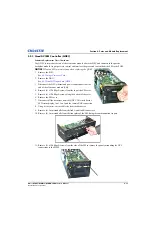
Page 51: ...Remove the two fan pack harnesses from the QDEC 4 Remove 1 1 Phillips screw from the side of the EM by the LED Status 5 Disconnect and remove the fan pack assembly 4 5 6 LED Status Display Estimated Replacement Time 15 minutes The LED status display is located on the face of the EM It provides a visual representation of the current projector status and display any error codes that are generated NO...

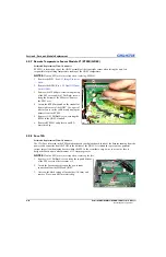
Page 52: ...e a pair of side cutters to cut the cable tie and unplug the harness from the RTSM 5 Remove 1 1 Phillips screw securing the RTSM to the QDEC standoff 6 Remove RTSM 1 and place in an ESD protective bag 4 5 8 Fuse 12A Estimated Replacement Time 10 minutes The 12A Fuse is located in the EM behind the passive backplane board inside of the harness running from the power cable connector from the PHM to ...

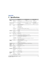
Page 53: ...and control Screen to screen ArrayLOC automatic brightness and color management Individual Comprehensive Color Adjustment CCA Optical lens type Low distortion zero offset short throw fixed lens with field curvature correction 0 69 1 throw for SXGA 0 64 1 throw for WUXGA screen size range 40 100 diagonal brightness uniformity Brightness uniformity control provides up to 100 uniformity capability fo...

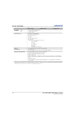
Page 54: ...emote keypad with easy to use menu system Multiple set up memories to manage multiple input sources Extensive scaling capability Window screen processing external inputs can be displayed across an array of screens up to 3 x 3 without an external processor a single input must be distributed to all cubes or it can be daisy chained through the cube s optional Twin HDMI module 3x redundant cooling fan...

Page 55: ... 1 020 100368 05 Rev 1 06 2012 6 Interconnections The Entero RPMSP RPMWU RPMHD LED01 interconnect diagram illustrates the path of electrical connections between modules Manufacturer s part numbers are included NOTE Part numbers are subject to change ...

Page 56: ......

Page 57: ...Section 6 Interconnections Entero RPMSP RPMWU LED01 Service Manual 6 3 020 100368 05 Rev 1 06 12 6 1 Interconnect Drawing ...

Page 58: ......

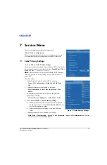
Page 59: ...rectly with ArrayLOC turned OFF To update values 1 Bright ColorLOC must be turned OFF by selecting ArrayLOC Configuration Bright ColorLOC Mode Off 2 Color adjustment must be disabled by selecting Color Saturation Select Color Adjustment Max Drives 3 LED brightness should be set to native or the preferred projector by selecting Advanced Color Adjustment Color Mode Native 4 Go to Service Menu Color ...

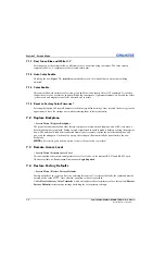
Page 60: ...ice Menu Replace Backplane The projector serial number and other factory settings are located on the backplane and will be lost when a defective backplane is replaced Settings must be transferred to another module before powering the projector down The unit should then be disconnected from all power sources replace the defective backplane and power up the unit again On the next power up the settin...

Page 61: ...have been configured on the web interface Use this control to delete all of these events from the system Once selected an option to cancel is provided 7 7 Status Service Menu Status Choosing this item provides information specific to the projector 7 8 Default Color Adjustment Service Menu Default Color Adjustment This specifies the default color adjustment to use for each new channel It allows the...

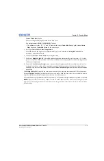
Page 62: ... native color settings menu Measure Native Mode is selected by default This disables all projector features that may interfere with accurate primary measurement including Bright ColorLOC It will also select a default duty cycle 2 Measure Native Red Green Blue X Y As each menu item is selected the test pattern color will change Using a color meter measure the x and y coordinates for each color Use ...

Page 63: ...target native white color temperature 8 From the Color Primary Settings menu measure the color primary and white coordinates with a color meter and enter these values in the appropriate controls For the most part the values for the primaries should be very similar or the same as those in the Native Color Settings menu but the white coordinates may differ With Bright ColorLOC enabled the color sens...

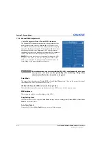
Page 64: ...is either OFF or in Fixed mode In all other Bright ColorLOC modes the Color Mode in this menu should be set to native These adjustments can turn on multiple RGB LEDs simultaneously which uses more power and increases the possibility of overheating Using these adjustments will also desaturate the color gamut Color Mode The menu allows the selection of Native EBU or User Color Mode presets These are...

Page 65: ...etting of the color temperature slide bar Lower numbers give a reddish white while higher numbers appear bluish There are four standard settings 9300 K is close to the white of many computer monitors 6500 K is the standard for color video in both standard and high definition forms 5400 K is a standard for graphics and black and white video 3200 K is useful if the projected image is to be filmed or...

Page 66: ...and apply them to the current color adjustment 7 9 4 Color Saturation Color Management Menu Color Saturation This menu allows the primary colors red green and blue to be adjusted by specifying the amount of each of the three native colors produced by the optical system that are combined to produce each of the primary colors This menu and the Color Adjustments by X Y menu accomplish the same thing ...

Page 67: ...gamut is smaller than the native projector capability 7 10 2 ArrayLOC Group The ArrayLOC Group identifies a subset of projectors that run with the same ArrayLOC settings 7 10 3 Broadcast Interval This is the interval in seconds between ArrayLOC projector communication and is normally set to 1 It can be changed using the numeric keypad on the remote 7 10 4 Adjustment Interval This is the interval i...

Page 68: ......

Page 69: ......
Page 70: ...6877 8737 Beijing ph 86 10 6561 0240 Shanghai ph 86 21 6278 7708 Corporate offices Worldwide offices Japan ph 81 3 3599 7481 South Korea ph 82 2 702 1601 For the most current technical documentation please visit www christiedigital com USA Cypress ph 714 236 8610 Canada Kitchener ph 519 744 8005 United Kingdom ph 44 118 977 8000 France ph 33 0 1 41 21 00 36 Germany ph 49 2161 664540 Eastern Europe...

Reviews: