3-60
M Series User Manual
020-100009-05 Rev. 1 (09-2010)
Section 3: Operation
3.13 Remote Control of the Projector
As an alternative to using a keypad, most projector functions can be controlled remotely, typically at a
controller such as a PC, via a web interface.
VIA ASCII MESSAGING —
Connect a serial link between your controller and the RS-232 or RS-422 port
(recommended), or open an Ethernet socket (i.e., Telnet) between your controller and the valid projector
address. Valid ASCII codes and messages are documented in the
Christie Serial Communications
document
available at the Christie website.
VIA WEB INTERFACE —
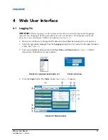
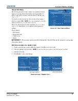
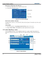
Connect the PC to the projector’s Ethernet port. In the web browser (i.e., Internet
Explorer), enter the IP address of the projector you wish to control. This will prompt a login screen. The
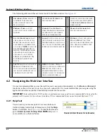
default login ids are: admin, service, and guest. Up to a maximum of 3 users can connect at any given time.
Two users can use the same account to log in. Each user will see a different set of tabs. The default passwords
can be edited by an administrator or a service user in the Admin tab. Guest users will not see this tab. Basic
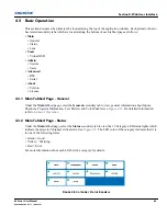
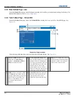
operations of the projector can be controlled from this interface and the Virtual OSD can be accessed from
here.
3.14 Alarm Conditions
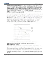
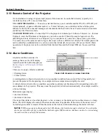
An alarm condition consists of a
message that is on the LCD display
located beside the built-in keypad, see
Section Figure 3-45 Example of Alarm
Condition
.
There are two types of alarm conditions:
• Warning Alarm
• Critical Alarm
A warning alarm is shown when an error or a non-optimal condition has occurred. That will generally not
prevent the projector from operating. An example is when a temperature is slightly elevated.
A critical alarm is shown when a condition occurs that could prevent the projector from operating and could
cause damage to the projector. This may cause the projector to shut down automatically. An example would be
a fan not running.
Both alarm types display:
• the item of alarm
• the status of the item
The item of the alarm can be either physical, i.e. fan or sensor, or the alarm can be a software issue, i.e. lamp
driver. The LCD displays the status of the item and its units; if applicable. If the status of the item is out of
normal range an alarm is created. When the status of the item is within normal range the alarm will clear.
NOTES:
1)
When an alarm is displayed in the LCD display, the built-in keypad is disabled. To confirm the
alarm, press the OK soft key to enable the built-in keypad
.
2)
The alarm condition can also be viewed using
the remote in the read only Status menu.
F
IGURE
3-45 E
XAMPLE OF
A
LARM
C
ONDITION
Summary of Contents for M Series
Page 1: ...M Series U S E R M A N U A L 020 100009 05 ...
Page 2: ......
Page 3: ...M Series U S E R M A N U A L 020 100009 05 ...
Page 14: ......
Page 46: ......
Page 120: ......
Page 131: ...Section 6 Troubleshooting M Series User Manual 6 7 020 100009 05 Rev 1 09 2010 FIGURE 6 1 ...
Page 132: ......
Page 148: ......
Page 152: ......
Page 167: ......


