4-10
M Series User Manual
020-100009-05 Rev. 1 09-2010
Section 4: Web User Interface
T
O
A
DD A
S
CHEDULED
E
VENT
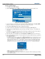
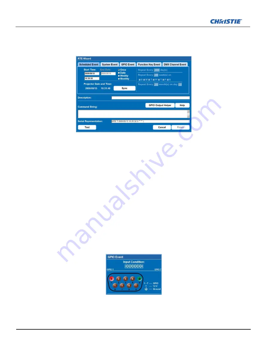
1. Click
Add
to open the
RTE Wizard
.
2. Select the
Scheduled Event
tab.
NOTE:
The scheduled tab is always selected by default on add.
F
IGURE
4-14 S
CHEDULED
E
VENT
W
INDOW
3. Select the frequency option for the event by selecting either
Once
,
Daily
,
Weekly
, or
Monthly
.
NOTE:
End Date is enabled when Daily, Weekly or Monthly repeat options are selected.
4. Click within the
Start Time
field to open a calendar pop-up window.
5. Navigate to and choose a desired date. The selected date will populate the
Start Time
field.
6. In the field below the
Start Time
field, enter a start time in the format “hr:min:sec”. The default is the
current time.
7. Click
Sync
to set the computer and projector time to be the same; otherwise,
the event will run based on
the projector time.
NOTE:
Synching the projector time to be that of your system time.
8. Enter a description of the scheduled event in the
Description
field.
NOTE:
Maximum of 100 characters.
9. Enter a serial command or a sequence of serial commands, with which you wish the projector to perform in
the
Command String
box.
• If a
GPIO
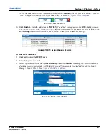
command string is needed, click the
GPIO Output Helper
button for instructions on how to
create the command structure.
NOTES: 1)
The
Output
field contains 7 blocks which refer to the 7 I/O
pins on the GPIO connector. Pin 1 = +12V and Pin 5 = Ground. These are not included.
2)
Clicking a
block toggles between H, L, and X.
3)
If the Pulse check box is selected, those I/O Pins defined will
pulse high or low. See
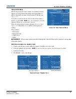
Figure 4-15 GPIO Output Helper
. See
Appendix B:
for detailed information.
F
IGURE
4-15 GPIO O
UTPUT
H
ELPER
•
NOTE
:
Serial Representation
box is read only.
• Click the
Help
button for a description of special RTE commands available for adding loops and delays
to the command sequence.
Summary of Contents for M Series
Page 1: ...M Series U S E R M A N U A L 020 100009 05 ...
Page 2: ......
Page 3: ...M Series U S E R M A N U A L 020 100009 05 ...
Page 14: ......
Page 46: ......
Page 120: ......
Page 131: ...Section 6 Troubleshooting M Series User Manual 6 7 020 100009 05 Rev 1 09 2010 FIGURE 6 1 ...
Page 132: ......
Page 148: ......
Page 152: ......
Page 167: ......

