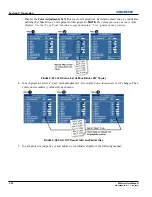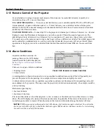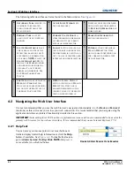
4-12
M Series User Manual
020-100009-05 Rev. 1 09-2010
Section 4: Web User Interface
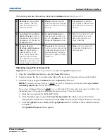
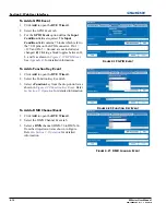
To Add a GPIO Event
1. Click
Add
to open the
RTE Wizard
.
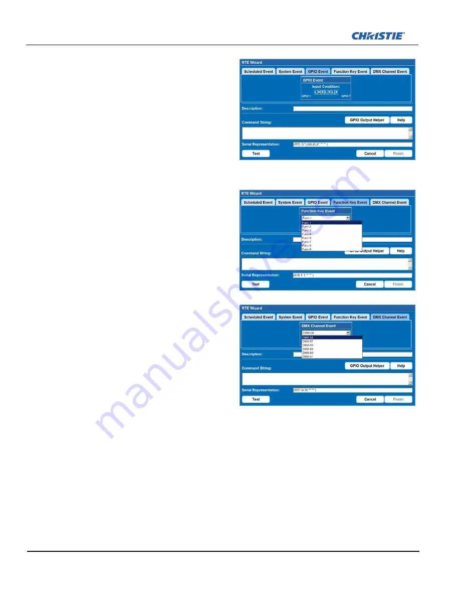
2. Select the GPIO Event tab.
3. For the
GPIO Event
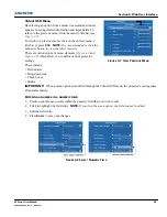
option define the
Input
Condition
field as required. The
Input
Condition
field contains 7 blocks which refer to
the 7 I/O pins on the GPIO connector. Pin 1 =
+12V and Pin 5 = Ground are not included or
changed.
2)
Clicking a block toggles between H,
L, and X as shown in
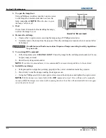
Figure 4-19 GPIO Event
.
See
Appendix B:
for detailed information.
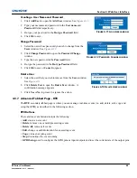
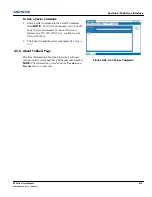
To Add a Function Key Event
1. Click
Add
to open the
RTE Wizard
.
2. Select the Function Key Event tab.
3. Select a
Function
key from the drop-down list as
shown in
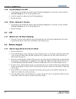
Figure 4-20 Function Key Event
. Refer
to
Section 3: Operation
for detailed information.
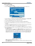
To Add a DMX Channel Event
1. Click
Add
to open the
RTE Wizard
.
2. Select the DMX Channel Event tab.
3. Select a
DMX
channel (DMX-56 to DMX-61)
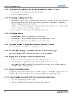
from the drop-down list as shown in Figure.
Refer to
Section 3: Operation
for detailed
information.
F
IGURE
4-19 GPIO E
VENT
F
IGURE
4-20 F
UNCTION
K
EY
E
VENT
F
IGURE
4-21 DMX C
HANNEL
E
VENT
Summary of Contents for M Series
Page 1: ...M Series U S E R M A N U A L 020 100009 05 ...
Page 2: ......
Page 3: ...M Series U S E R M A N U A L 020 100009 05 ...
Page 14: ......
Page 46: ......
Page 120: ......
Page 131: ...Section 6 Troubleshooting M Series User Manual 6 7 020 100009 05 Rev 1 09 2010 FIGURE 6 1 ...
Page 132: ......
Page 148: ......
Page 152: ......
Page 167: ......

