C-4
M Series User Manual
020-100009-05 Rev. 1 (09-2010)
Appendix C: DMX / ArtNet
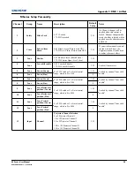
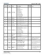
Channel
Group
Name
Description
Default
Value
Notes
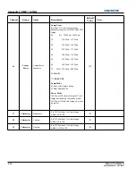
14
Input
Input
Input Selection
0 to 9 Slot 1, Input 1
10 to 19 Slot 1, Input 2
....
50 to 59 Slot 1, Input 6
60 to 69 Slot 2, Input 1
....
110 to 119 Slot 2, Input 6
120 to 129 Slot 3, Input 1
....
170 to 179 Slot 3, Input 6
180 to 189 Slot 4, Input 1
....
230 to 239 Slot 4, Input 6
255
Will not change input on default
15
Image
Image Freeze
0-85 Unfreeze image
172-255 Freeze Image
0
16
Lamps/
Power
Power
0-85 Power Off (Switch lamps off, cool
lamps down and go to Standby mode)
172-255 Power On (Switch lamps on,
warm up mode)
128
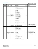
A 5 second timer will be used
before executing a power state
change. If the slider moves out
of the On/Off range within the 5
seconds, the timer will be can-
celled.
Will not change power stat on
default.
17
Image
Size
0 to 255 Scaled as % of total control
range, which is 200 to 4000
67
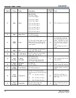
18
Image
Vertical Stretch
0 to 255 Scaled as % of total control
range, which is 200 to 3000
91
19
Setup
Functions
Projector
Orientation
0-49 Front Projection
50-99 Rear Projection
100-149 Front Projection Inverted
150-199 Rear Projection Inverted
255
Will not change projector orien-
tation on default.
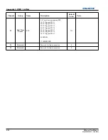
20
Setup
Functions
On Screen
Display
0-85 OSD Off
172-255 OSD On
128
Will not change OSD on default.
21
Setup
Functions
Lens Calibrate
172-255 Run calibration
0
Locked by channel “Lens shift
enable”.
22
Setup
Functions
Lamp Power
Scaled as % of total control range.
Examples are given for 350W and 200W
lamps:
0 0% 300 Watt / 150 Watt
....
127 50% 335 Watt / 175 Watt
....
255 100% 370 Watt / 200 Watt
255
Depends on what lamps are
used, power rating may be dif-
ferent scale.
23
Setup
Functions
Lamp Mode
0-85 Auto Select Single lamp
172-255 Dual Lamp Mode
128
Will not change lamp mode on
default.
Summary of Contents for M Series
Page 1: ...M Series U S E R M A N U A L 020 100009 05 ...
Page 2: ......
Page 3: ...M Series U S E R M A N U A L 020 100009 05 ...
Page 14: ......
Page 46: ......
Page 120: ......
Page 131: ...Section 6 Troubleshooting M Series User Manual 6 7 020 100009 05 Rev 1 09 2010 FIGURE 6 1 ...
Page 132: ......
Page 148: ......
Page 152: ......
Page 167: ......


