2-6
M Series User Manual
020-100009-05 Rev. 1 (09-2010)
Section 2: Installation and Setup
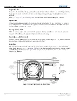
Adjustable Feet
Located on the underside of the projector are three adjustable feet. Raise or lower these feet when positioning
the projector to ensure it is level on all sides so the displayed image will appear rectangular without any
keystone.
Refer to
2.2.5 Adjusting Projector Height/Tilt
for instructions on how to adjust the projector’s feet.
Input Panel
All source connections are made to the input panel located at the back of the projector. Any of the available
optional input cards can be installed in the 4 option card slots. The slots are labelled 1 through 4. All option
cards have LEDs to indicate their status.
Cooling and Air Vents
There are numerous air vents located around the projector. It is important these vents remain unobstructed.
Adequate airflow through the projector will prevent it from overheating.
Kensington Lock Attachment
Located at the rear of the projector to the left of the AC receptacle, is a Kensington lock attachment point. This
provides the ability to secure the projector against possible theft.
Lamp Door
The lamp doors are located at the side of the projector, which provides easy access to the lamp module for
replacement. Refer to
Section 5.3 Replacing the Lamps
. The lamp doors are fitted with safety interlocks which
switch the lamp off when the door is opened. The lamp doors are provided with clear windows to indicate
when the lamps are on.
F
IGURE
2-8 A
BOUT THE
P
ROJECTOR
- F
RONT
V
IEW
Summary of Contents for M Series
Page 1: ...M Series U S E R M A N U A L 020 100009 05 ...
Page 2: ......
Page 3: ...M Series U S E R M A N U A L 020 100009 05 ...
Page 14: ......
Page 46: ......
Page 120: ......
Page 131: ...Section 6 Troubleshooting M Series User Manual 6 7 020 100009 05 Rev 1 09 2010 FIGURE 6 1 ...
Page 132: ......
Page 148: ......
Page 152: ......
Page 167: ......

