2-10
M Series User Manual
020-100009-05 Rev. 1 (09-2010)
Section 2: Installation and Setup
2.2.3 Projector Position and Mounting
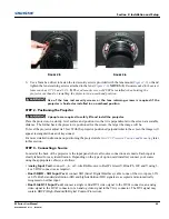
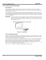
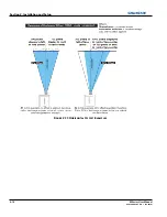
Throw Distance
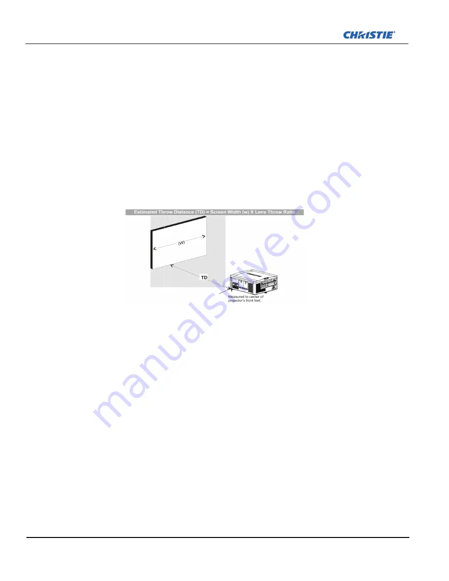
Throw distance is the distance measured from your projector’s front feet to the screen. This calculation
determines if there is enough room to install your projector with a desired screen size and if the image will be
of the right size for your screen.
To estimate the throw distance take the horizontal width of the screen and multiply it by the lens throw ratio.
The result determines approximately the distance the projector should be positioned from the screen to project
a focused image large enough to fill the screen. For example, using a 0.73:1 lens, throw distance would roughly
be 0.73 x screen width.
IMPORTANT!
Use the lens and screen size to calculate the precise throw distance using the tables provided
in the Dealer Section of the Christie Website, PN 020-100221-XX. Due to lens manufacturing
tolerances for lens focal length, actual throw distance can vary
±
5% between lenses with the
same nominal throw ratio.
Vertical and horizontal position
The correct vertical and horizontal position of the projector in relation to the screen depends on the lens type
and the screen size. Ideally, the projector should be positioned perpendicular to the screen. This way, the image
will appear rectangular instead of keystoned (trapezoidal).
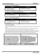
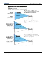
The vertical position of the image can be offset (that is moved above or below the optical axis) by adjusting the
motorized lens mount. The amount of vertical offset available depends on the type of lens installed in the
projector and can be limited if horizontal offset has been applied. Vertical offset can be expressed as the
percent of half the image height or the number of pixels of shift from lens center. Refer to
Figure 2-12 Vertical
Offset Examples
for illustrated examples of vertical offset.
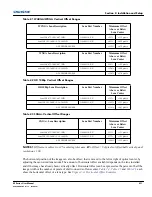
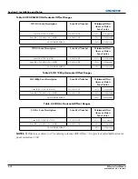
Table 2.1
,
Table 2.2
and
Table 2.3
specify the vertical offset of each type of lens.
F
IGURE
2-11 T
HROW
D
ISTANCE
Summary of Contents for M Series
Page 1: ...M Series U S E R M A N U A L 020 100009 05 ...
Page 2: ......
Page 3: ...M Series U S E R M A N U A L 020 100009 05 ...
Page 14: ......
Page 46: ......
Page 120: ......
Page 131: ...Section 6 Troubleshooting M Series User Manual 6 7 020 100009 05 Rev 1 09 2010 FIGURE 6 1 ...
Page 132: ......
Page 148: ......
Page 152: ......
Page 167: ......


