Section 2: Installation and Setup
M Series User Manual
2-17
020-100009-05 Rev. 1 (09-2010)
2.2.7 Advanced Optical Alignment
Boresight Alignment Procedure
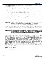
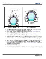
1. Display the Boresight Test Pattern by pressing the
T
EST
key on the remote keypad or use the built-in
keypad and press the soft key that displays Test on the LCD display, then
U
P
A
RROW
K
EY
to cycle to
Boresight, then Enter, see
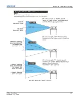
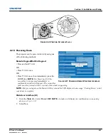
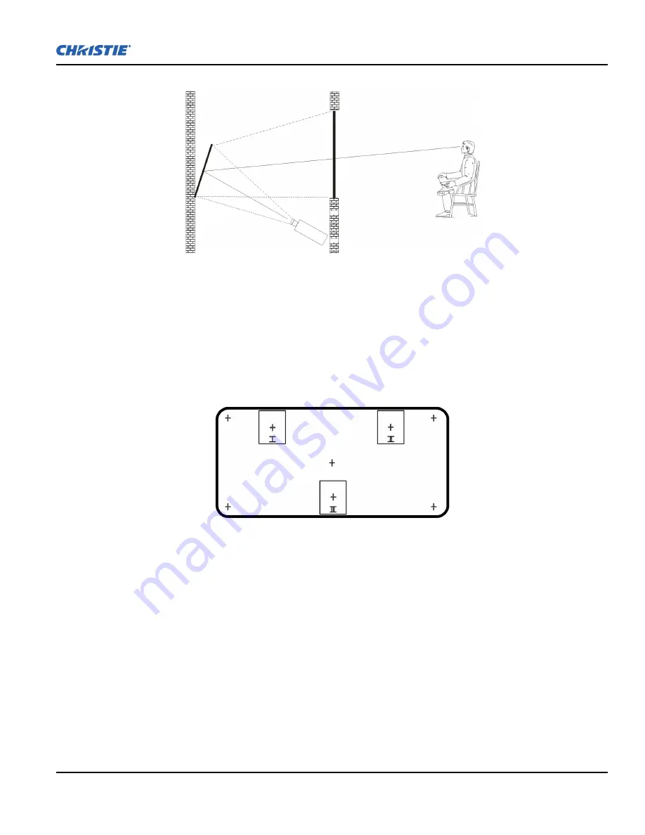
Figure 2-17 Boresight Pattern
.
2. Focus the image on cross-hair pattern I. Evaluate the focus on cross-hair image II and III. If all 3 images
are in focus, no further action is required. If boresight is required see step 3.
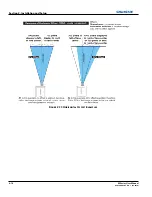
3. If boresight is required, refer to
Figure 2-18 Cross-Hair Pattern
to understand how the adjustment screws
on the lens mount affect the corresponding cross-hairs on the test pattern.
NOTE:
The capscrew,
(
Figure 2-
19
)
may be under a plastic cap, remove and retain before adjusting.
4. Use a 5mm Allen™ key to loosen the 3 locking setscrews on the lens mount, see
Figure 2-19 Screw
Locations
, below.
NOTE:
The setscrews must be backed out several turns, so that they do not contact the
inner lens mount plate.
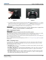
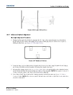
F
IGURE
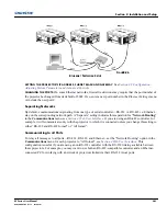
2-16 F
OLDED
O
PTICAL
P
ATH
F
IGURE
2-17 B
ORESIGHT
P
ATTERN
Summary of Contents for M Series
Page 1: ...M Series U S E R M A N U A L 020 100009 05 ...
Page 2: ......
Page 3: ...M Series U S E R M A N U A L 020 100009 05 ...
Page 14: ......
Page 46: ......
Page 120: ......
Page 131: ...Section 6 Troubleshooting M Series User Manual 6 7 020 100009 05 Rev 1 09 2010 FIGURE 6 1 ...
Page 132: ......
Page 148: ......
Page 152: ......
Page 167: ......

