2-22
M Series User Manual
020-100009-05 Rev. 1 (09-2010)
Section 2: Installation and Setup
MIXED NETWORK
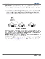
: To control multiple projectors with a computer/controller having an RS-422 interface:
1. Set them all to the same baud rate as your RS-422 controller.
NOTE:
You must enable this combination of
RS-422 and RS-232 in the
Communications
menu. Set the
“
Network Routing
”
option to
“
RS-232 and
RS-422 Joined
”,
see
Section 4 Web User Interface.
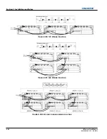
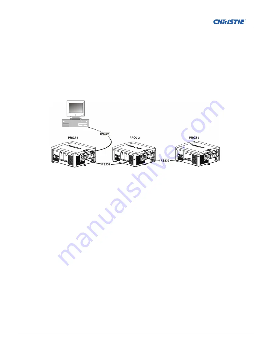
2. Chain the projectors together by connecting an
RS-232
OUT (Null Cable) of the first projector (already
connected to the computer/controller through the
RS-422
port straight thru to an
RS-232
IN on the next
projector in the chains). Continue connecting projectors in this manner until you’ve reached the last
projector in the chain, so that only the last projector has one unused port
RS-232
OUT, see
Figure 2-25
Mixed Network
.
Communication parameters, such as baud rate, must be set to match the particular controlling device, before
connecting as a network—refer to the documentation that came with your controlling device to determine the
proper baud rate. See
Section 3 Operation
for help changing the projector baud rate. To communicate to all
projectors, set the Network Routing to “RS-232 and RS-422 Joined”.
NOTES:
1)
Connect only properly wired serial communication cables.
2)
Each RS-232 communication cable
should be no more than 50 feet in length. Use high quality cables.
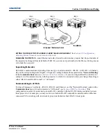
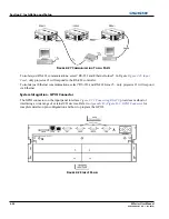
ETHERNET NETWORK SETUP
: To add one or more projectors to an Ethernet network, use standard CAT5 cable
to connect each projector’s Ethernet port to a hub belonging to the network. A controller or PC must also be
connected to the hub, see
Figure 2-26 Ethernet Network Setup
.
NOTE:
A wireless router can be used to
communicate to the projectors via 802.11b/g.
F
IGURE
2-25 M
IXED
N
ETWORK
Summary of Contents for M Series
Page 1: ...M Series U S E R M A N U A L 020 100009 05 ...
Page 2: ......
Page 3: ...M Series U S E R M A N U A L 020 100009 05 ...
Page 14: ......
Page 46: ......
Page 120: ......
Page 131: ...Section 6 Troubleshooting M Series User Manual 6 7 020 100009 05 Rev 1 09 2010 FIGURE 6 1 ...
Page 132: ......
Page 148: ......
Page 152: ......
Page 167: ......

