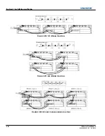
2-24
M Series User Manual
020-100009-05 Rev. 1 (09-2010)
Section 2: Installation and Setup
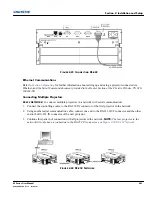
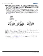
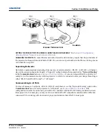
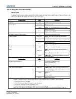
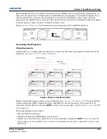
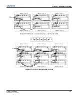
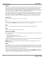
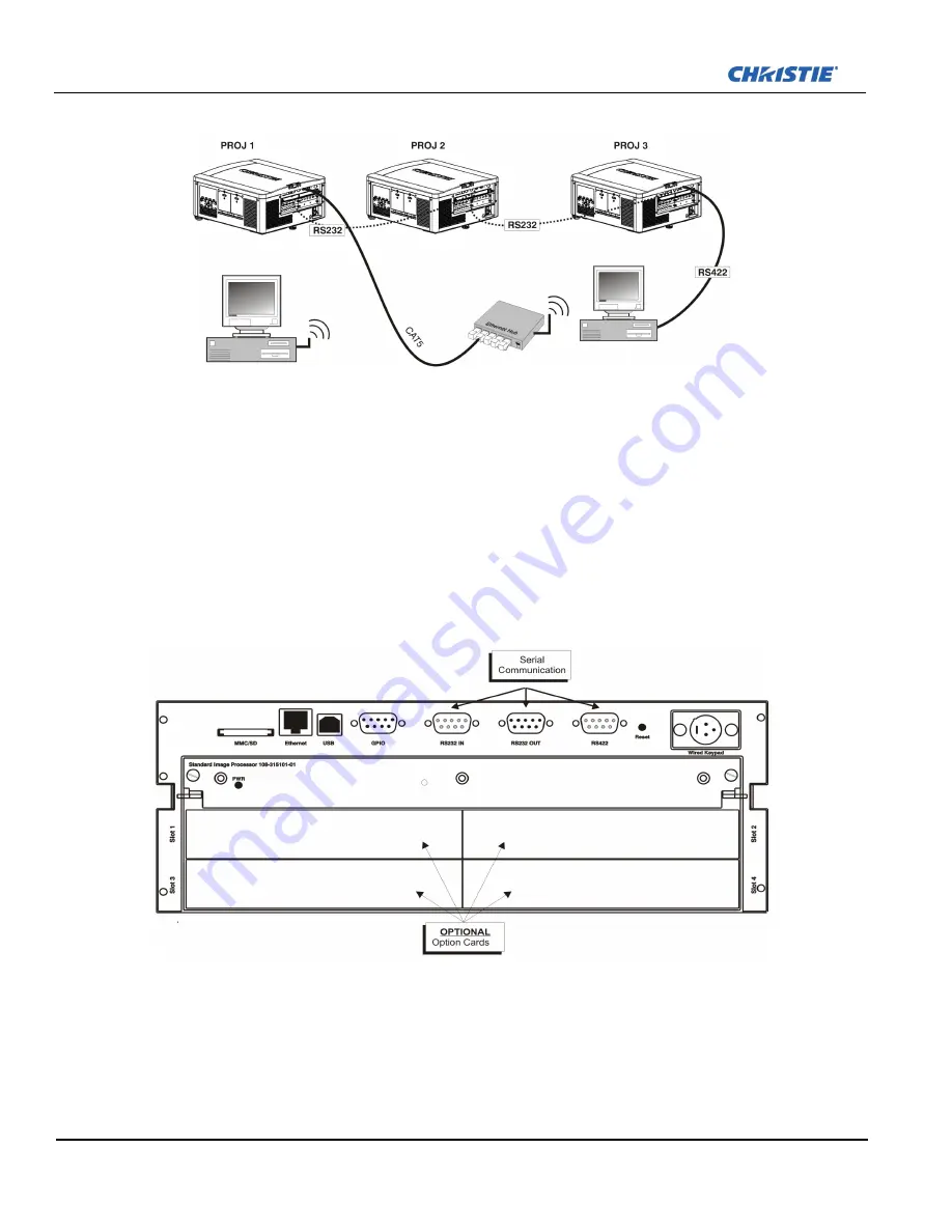
To isolate just RS-422 communications, select “RS-232 and Ethernet Joined”. In Figure
Figure 2-28 Input
Panel
, only projector #1 will respond to the RS-422 controller.
To isolate just Ethernet communications, select “RS-232 and RS-422 Joined”—only projector #1 will respond
via Ethernet.
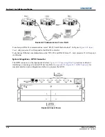
System Integration - GPIO Connector
The GPIO connector on the input panel interface
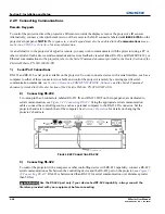
Figure 2-23 Connecting RS-422
, provides a method of
interfacing a wide range of external I/O devices. Refer to
Appendix B:
,
Figure B-1- GPIO Connector
for
complete details on pin configuration and how to program the GPIO.
F
IGURE
2-27 C
OMMUNICATING
T
O
A
LL
P
ORTS
F
IGURE
2-28 I
NPUT
P
ANEL
Summary of Contents for M Series
Page 1: ...M Series U S E R M A N U A L 020 100009 05 ...
Page 2: ......
Page 3: ...M Series U S E R M A N U A L 020 100009 05 ...
Page 14: ......
Page 46: ......
Page 120: ......
Page 131: ...Section 6 Troubleshooting M Series User Manual 6 7 020 100009 05 Rev 1 09 2010 FIGURE 6 1 ...
Page 132: ......
Page 148: ......
Page 152: ......
Page 167: ......

