Section 2: Installation and Setup
M Series User Manual
2-25
020-100009-05 Rev. 1 (09-2010)
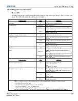
2.2.10 Projector Communications
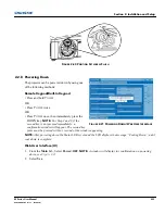
Status LEDs
Looking from the back of the projector, the LEDs represent, from left to right; Lamp 1, Lamp 2, Power, and
Status. The LEDs will display the colors as sho wn below:
Projector State
LEDs
LED State
Hard Boot
All
All LEDs amber - means please wait
Standby Mode
Lamp 1 & 2
Off
- lamps are off
Power
Amber
- AC is present but projector is off or standby
Shutter
Green
- shutter is open
Amber
- shutter is closed
Warm-up (Powering ON from standby)
All
LEDs cycle green from left to right
Normal Operation
Lamp 1 & 2
Amber
- lamp time has expired and lamp should be
replaced
Power
Green
- projector is powered up and operating normally
Shutter
Green
- shutter is open
Amber
- shutter is closed
Cool-down
All
LEDs cycle amber from left to right
Error
Lamp 1 & 2
Amber
- lamp time has expired and lamp should be
replaced
Flashing Red
- lamp has malfunctioned
Power
Flashing Red
- error has occurred. Details are displayed
on the status display
Projector State
LEDs
LED State
Software Upgrade in progress
All
The pattern will alternate between:
Amber, Off, Amber, Off
and
Off, Amber, Off, Amber
Lamp Regeneration in progress
Lamp 1 & 2
Flashing Green
- the lamp is being switched off for its
regeneration period to extend lamp life (typically 15 min-
utes every 24 hours)
Power
Green
- on
or
Amber
- standby
Shutter
Green
- shutter is open
NOTE:
A condition occurs on the first power on after a software upgrade, and is indicated by all the following:
• The Status LEDs are cycling green
• The LCD displays the warning "Image Processor Upgrading"
• The LED on the Image Processor card flashes green
• The Web page shows a warning that the Image processor card is upgrading.
When this occurs, the projector should not be AC power cycled and the Image Processor card should not be removed.
Summary of Contents for M Series
Page 1: ...M Series U S E R M A N U A L 020 100009 05 ...
Page 2: ......
Page 3: ...M Series U S E R M A N U A L 020 100009 05 ...
Page 14: ......
Page 46: ......
Page 120: ......
Page 131: ...Section 6 Troubleshooting M Series User Manual 6 7 020 100009 05 Rev 1 09 2010 FIGURE 6 1 ...
Page 132: ......
Page 148: ......
Page 152: ......
Page 167: ......

