Section 3: Operation
M Series User Manual
3-29
020-100009-05 Rev. 1 (09-2010)
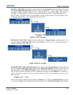
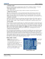
The 2.22 curve is a power curve typically used to encode graphics and video sources, see
Figure 3-30 Gamma
Curve
. The 'standard' curve (auto setup default) is a modified 2.22 curve with a small linear section in the black
that enhances the detail in darker areas of the projected content. Typically standard or 2.22 is used for all
sources. Alternatively, if neither default is ideal, apply a simple gamma curve by defining a custom power
function and slope. Select
Gamma Function
from the drop down list to enable the Gamma Function and
Gamma Slope controls. For more complex non-standard gamma curves, a user-defined curve created
externally and downloaded to the projector can be used (requires separate PC-based Arbitrary Gamma
software application to create the table and the Web UI to download it).
NOTE:
If any of these special user
curves have been installed, their names will appear in the Gamma Table pull-down list.
•
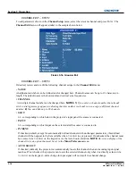
GAMMA FUNCTION
- Defines the base gamma power curve used when the base gamma table value is set
to
Gamma Function
. This value, combined with gamma slope setting determines the base gamma table to
be used as the custom base table. The curve is generally a power curve with a small linear segment at the
bottom defined by the slope.
•
GAMMA SLOPE
- This control defines a slope to be used for the base custom gamma table for a small
section at the bottom of the curve. This slope can be used to bring in or out the low level blacks in the image.
This slope combined with the gamma function, define the custom gamma table.
DETAIL SETTINGS
Adjusts the sharpness of the image. Setting detail above the halfway point can introduce ‘noise’ in the image.
Lower settings can improve a noisy signal.
• DETAIL -
Adjust the sharpness of the image. Setting detail above the halfway-point can introduce noise in
the image. Lower settings can improve a noisy signal. This command does not take effect unless the
minimum change required in the Detail Threshold control is reached.
• TEXTURE ENHANCEMENT -
Applies texture detail enhancement based on adaptive horizontal, vertical,
and diagonal large edge and small edge enhancement processes.
•
DETAIL THRESHOLD
- Selects a filter sensitivity to noise. A higher value may improve noisy sources
especially for higher settings of detail.
•
DETAIL OVERSHOOT
- Minimizes ringing on the enhanced edges detail and texture effects.
•
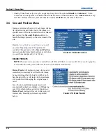
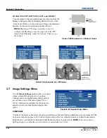
SPLIT SCREEN
-
Allows a snap shot of the main image to be presented on the right side of the
screen to allow evaluation of advanced image processing features. All resizing controls are
honoured on both images; however, image processing controls only happen on the left side image.
Changing inputs, channels or test patterns will disable this control.
NOTE:
PIP and Tiling operation
must be disabled prior to enabling this control.
NOISE REDUCTION SETTINGS
•
NOISE REDUCTION -
Selects a filter sensitivity to noise. A higher value may improve noisy sources, but
it will soften the image.
• BLOCK ARTIFACT REDUCTION -
Locates and reduces block edges produced by discrete cosine
transform (DCT) based compression processing.
• MOSQUITO NOISE REDUCTION -
Reduces mosquito artifacts around sharp edges in DCT based
compression by dynamically adapting to image content.
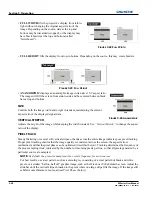
• SPLIT SCREEN -
Provides a snap shot of the main image to be presented on the right side of your screen to
allow evaluation of advanced image processing features. All resizing controls and input card features; such
as color/tint etc, are honoured on both images. However; image processing controls such as the detail-
texture, noise reduction and adaptive contrast features, only occur to the left side image. Changing inputs,
channels or test patterns will disable this control.
NOTE:
PIP operation must be disabled prior to enabling
this control.
Summary of Contents for M Series
Page 1: ...M Series U S E R M A N U A L 020 100009 05 ...
Page 2: ......
Page 3: ...M Series U S E R M A N U A L 020 100009 05 ...
Page 14: ......
Page 46: ......
Page 120: ......
Page 131: ...Section 6 Troubleshooting M Series User Manual 6 7 020 100009 05 Rev 1 09 2010 FIGURE 6 1 ...
Page 132: ......
Page 148: ......
Page 152: ......
Page 167: ......

