3-36
M Series User Manual
020-100009-05 Rev. 1 (09-2010)
Section 3: Operation
COMMUNICATIONS - S
UBMENU
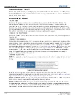
Defines and controls how single or multiple projectors are linked with each other and with a controlling device.
For detailed information refer to
the Serial Command document provided in the Dealer Section of the Christie
Website, PN 020-100224-XX.
SERIAL OPTIONS - S
UBMENU
• BAUD RATE
Determines the speed of communication to and from the projector on the RS-232 or RS-422 links. The
maximum rate for the RS-232 is 115200; for RS-422 it is 19200. Set the baud rate to match that of your
controlling device, such as your PC. Refer to the documentation for the controlling device to determine the
baud rate. In an existing network of projectors, if you discover that a projector has a different baud rate, use the
pull-down list and select the correct baud rate using the
E
NTER
key. Do not scroll this control with
L
EFT
A
RROW
K
EY
or
R
IGHT
A
RROW
K
EY
. Serial communication is always eight data bits, no parity.
• SERIAL FLOW CONTROL
Determines whether software flow control or no flow control is used when transmitting and receiving data on
the serial port.
• PROJECTOR ADDRESS
Enter a three-digit number (such as “001”) to assign or change a number to the projector currently in use. If the
current projector already has a number assigned, that number will appear here (for example “004” in the menu
shown below. Numerical identity for projectors enables you to communicate with a single projector within a
multiple-projector application (see also
P
ROJ
key in,
3.1 Using the Remote Keypad or Built-In Keypad
). If you
make a mistake in assigning or changing the projector number, press
E
XIT
to cancel.
NOTE:
When multiple
projectors are being used and you want to adjust the color for individual projectors to create one seamless
image, you must assign different numbers for each projector to allow switching back and forth between
projectors while adjustments are being made.
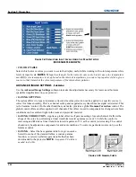
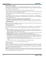
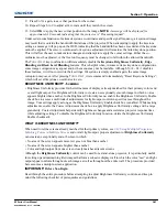
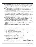
• NETWORK ROUTING
NOTE:
Not applicable for stand-alone projectors or simple serial networks with only one type of controller and
linking.
Separate -
Select “
Separate
” (factory default) to keep RS-232, RS-422 and Ethernet messages on their
respective paths instead of being broadcast to the other types of ports, refer to
Section 2 Installation and Setup,
Figure 2-22 Connecting RS-232
to
Figure 2-27 Communicating To All Ports
.
RS-232 and RS-422 Joined -
Messages originating from an RS-232 or RS-422 controller will be relayed to all
RS-232or RS-422 ports. Any Ethernet communication, however, will not.
RS-232 and Ethernet Joined -
Messages to and from the RS-232 ports will also be relayed to the Ethernet
port, and vice versa. Any RS-422 communications will be isolated. In the case of multiple Ethernet sessions
over the single Ethernet connector, input on the RS-232 port will be relayed to all Ethernet sessions; however,
input from any Ethernet session will only be relayed to the RS-232 ports.
F
IGURE
3-32 N
ETWORK
R
OUTING
L
IST
Summary of Contents for M Series
Page 1: ...M Series U S E R M A N U A L 020 100009 05 ...
Page 2: ......
Page 3: ...M Series U S E R M A N U A L 020 100009 05 ...
Page 14: ......
Page 46: ......
Page 120: ......
Page 131: ...Section 6 Troubleshooting M Series User Manual 6 7 020 100009 05 Rev 1 09 2010 FIGURE 6 1 ...
Page 132: ......
Page 148: ......
Page 152: ......
Page 167: ......

