Section 3: Operation
M Series User Manual
3-51
020-100009-05 Rev. 1 (09-2010)
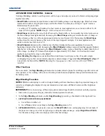
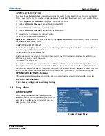
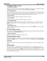
• INPUT LEVEL DETECTOR
The
Input Level Detector
check box enables specific thresholds for blacks and whites. Input levels that fall
below a specified level value (see below) are displayed as black, and all others are displayed as white. To use:
1. Enable
Input Level Detector
and display a continuous greyscale.
2. Set
Level Detector Threshold
to near black (such as 200).
3. Adjust Offsets to minimize area of black stripe.
4. Set
Level Detector Threshold
to near white (such as 800).
5. Adjust Gains to minimize area of white stripe.
• LEVEL DETECTOR THRESHOLD
Input Level Value
defines the value to be used by the
Input Level Detector
in recognizing blacks and whites.
See
Input Level Detector
, above.
• ASPECT RATIO OVERLAY
Check this box to display an overlay pattern over the image. The overlay shows the boxes corresponding to the
size and shape of different aspect ratios.
• TEST PATTERN COLOR SWAP
This function swaps the green and red color when drawing the Grid test pattern, and may be helpful when
adjusting convergence on the projector.
•
CALIBRATE LITELOC
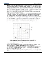
The LiteLoc calibration process must be run to calibrate the LiteLoc sensor on all model types. “Constant
Intensity” mode cannot operate correctly if the calibration has not been performed. The calibration must be
done in Dual Lamp mode, after the lamps have warmed up for at least 5 minutes.
NOTE:
The shutter will close
for the duration of the calibration, and will automatically open again when the calibration is complete.
OPTION CARD SETTINGS - S
UBMENU
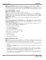
Allows adjustment of any settings specific to each option card that is currently installed in the projector.
DYNAMIC IRIS - S
UBMENU
Refer to
Image Settings>Advanced Image Settings
3.9
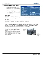
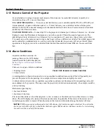
Lamp Menu
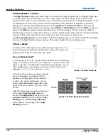
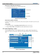
LAMP OPERATION
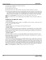
Select the operational mode to be assigned to the
lamp(s) from the Lamp Operation drop-down list. If
a lamp fails to strike on the first attempt, you can
attempt upto 3 more strikes.
F
IGURE
3-39 L
AMP
M
ENU
Summary of Contents for M Series
Page 1: ...M Series U S E R M A N U A L 020 100009 05 ...
Page 2: ......
Page 3: ...M Series U S E R M A N U A L 020 100009 05 ...
Page 14: ......
Page 46: ......
Page 120: ......
Page 131: ...Section 6 Troubleshooting M Series User Manual 6 7 020 100009 05 Rev 1 09 2010 FIGURE 6 1 ...
Page 132: ......
Page 148: ......
Page 152: ......
Page 167: ......

