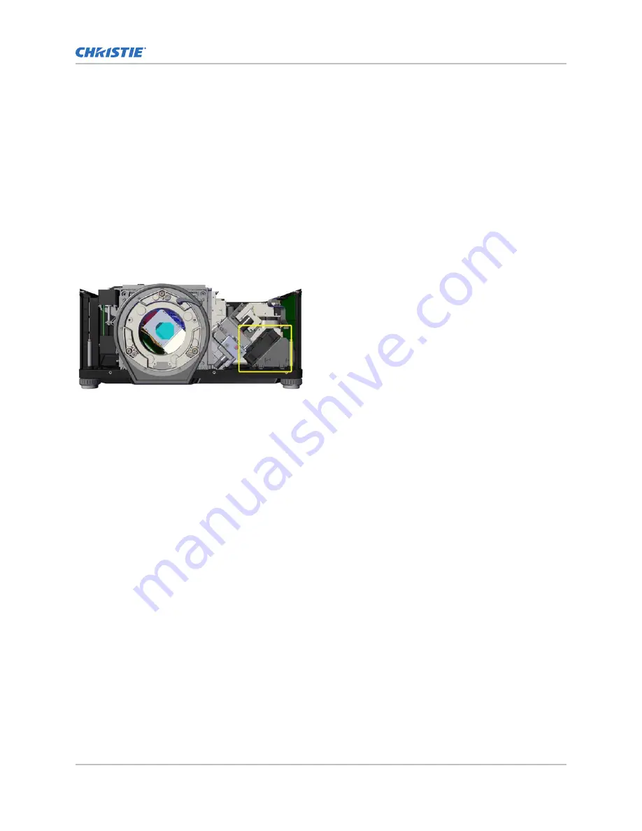
14. Remove the duct and the fan from the projector.
15. Remove the four screws securing the upper and lower portion of the duct together.
16. Remove four isolator pads holding the fan to the upper duct.
17. Remove fan #4.
18. To re-install, follow these steps in reverse order.
Removing the side exhaust fan (#9)
Fan #9 takes the warm air from inside the projector and removes it using an exhaust duct. The fan is
located underneath the optical assembly beside the printed circuit boards (PCBs) for the status display
control panel.
Estimated replacement time: 14 minutes.
1. Remove the top cover (on page 45).
2. Remove the front cover (on page 48).
3. Cut the cable tie.
4. Disconnect fan #9 at the quick disconnect coupling.
5. Remove the three screws holding exhaust duct to base.
6. Slide the fan and the base out of projector.
7. Remove four rubber isolators holding fan to duct.
Replacement isolator pads are part of the service kit.
8. Remove fan #9.
9. To re-install, follow these steps in reverse order.
Removing the intake and exhaust fans (#5 and
#6)
The screws securing the fans are also securing a grid on the inside of the light engine compartment.
The grid cannot be removed until the top compartment of the engine housing is removed.
Estimated replacement time: 20 minutes per fan.
Ventilation and cooling
M Series Service Guide
56
020-100551-11 Rev. 1 (01-2019)
Copyright
©
2019 Christie Digital Systems USA, Inc. All rights reserved.
Summary of Contents for M Series
Page 1: ...Service Guide 020 100551 11 M Series ...
Page 95: ......


