14. Grab the three power cables inside the card cage and slowly pull the card cage up and out of
the unit.
The cables slides out of the hole in the bottom of the card cage. Use caution when pulling
cables through this hole. Do not damage wire insulation.
15. To re-install, follow these steps in reverse order.
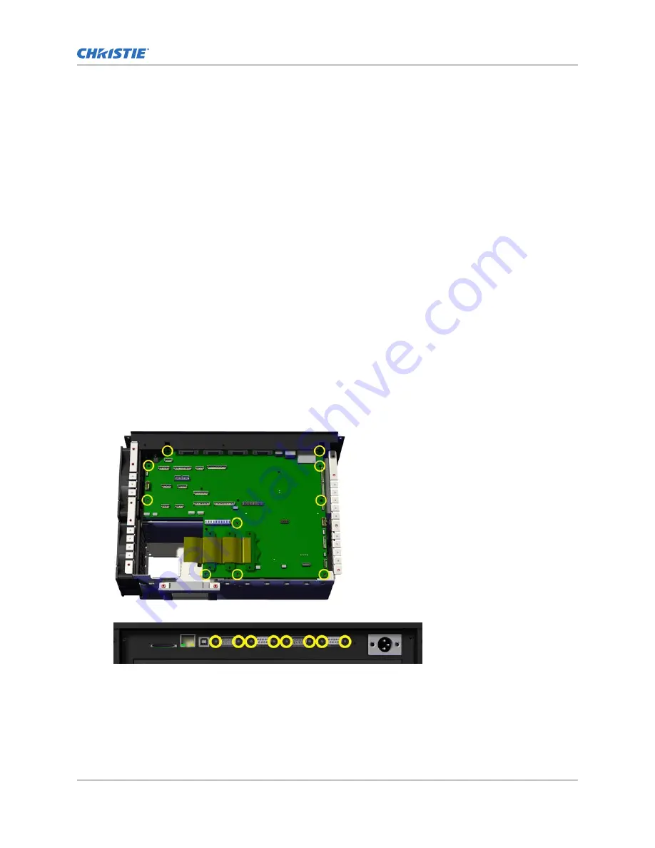
Removing the panel driver
The panel driver is located directly under the card cage plate. This board provides several different
interfaces, some of these include RS232 Input and Output, RS422 Input, GPIO, and Ethernet.
Interconnections include lens motor control, shutter, IRIS, light sensor, power supply control, and
board temperature.
Estimated replacement time: 20 minutes.
1. Remove the top cover (on page 45).
2. Remove the remote temperature sensor module (RTSM) #2 (on page 90).
3. Remove the card cage lid (on page 60).
4. Disconnect the following wires: J48, J65, J40, J38, J47, J42, J60, J50, J52, J54, J59, J43, J44,
J45, J26, J29, and J41.
5. Remove the card cage plate (on page 60).
6. Disconnect the three engine cable connections P86 (blue), P85 (green), and P84 (red) from the
panel driver.
7. Remove the 10 screws and the center standoff from the panel driver.
8. Remove the eight standoffs from the input face plate.
9. Remove the panel driver by pulling up and out.
The panel driver is connected underneath to the passive back plane (PBP).
10. To re-install, follow these steps in reverse order.
Electronics
M Series Service Guide
62
020-100551-11 Rev. 1 (01-2019)
Copyright
©
2019 Christie Digital Systems USA, Inc. All rights reserved.
Summary of Contents for M Series
Page 1: ...Service Guide 020 100551 11 M Series ...
Page 95: ......


