The lens security screws are required if the projector is hoisted or installed in an overhead
position.
10. Remove the front lens cap.
Removing the optical assembly
The optical assembly consists of the integrator, front optical, rear optical and light engine assemblies.
To remove the light engine start by removing the card cage lid, it connects to the bridge, and the
bridge connects to the light engine cover.
The optical assembly can be removed as one module from the projector. This module includes the light
engine cover, front and rear optical housings and the integrator housing.
Estimated replacement time: 50 minutes.
1. Remove the top cover (on page 45).
2. Remove the light engine intake duct (on page 81).
3. Disconnect fans #5 and #6 located on the light engine cover at the quick disconnect coupling.
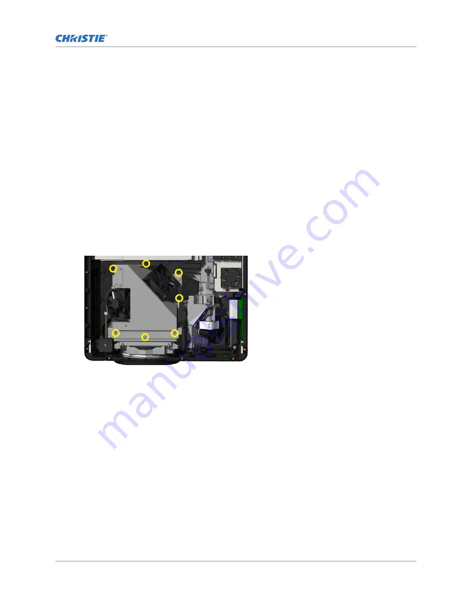
4. Remove the seven screws from the light engine cover to remove the top portion of the
housing.
5. Remove the card cage lid (on page 59).
6. Disconnect the shutter harness at the panel driver.
7. Remove the six screws and disconnect the three light engine LVDS cables at the panel driver.
8. Remove the bridge (on page 60).
9. Remove the light engine cover.
10. Remove the lamps (on page 81).
11. Remove the one screw from under each lamp door holding the side panel to the lamp
compartment.
12. Remove the two screws inside the lamp compartment through the top.
Optics
M Series Service Guide
78
020-100551-11 Rev. 1 (01-2019)
Copyright
©
2019 Christie Digital Systems USA, Inc. All rights reserved.
Summary of Contents for M Series
Page 1: ...Service Guide 020 100551 11 M Series ...
Page 95: ......


