20
Step 7:
Checks
1. Check the orderly installation and function of all bolted and plug con-
nections. Installation is then complete.
2. When everything is in order, familiarise yourself with the machine at
a light resistance setting and make the individual adjustments of the
footrests (28) and (34).
Note:
Please keep the tool set, the puller and the instructions carefully
because these may be required later for repairs or spare parts orders.
If you ever remove the covers (10) and (11), observe that these are attached
not only outwardly with the screws (64+65), but also inwardly at the rear end
of the cover with the screws (65).
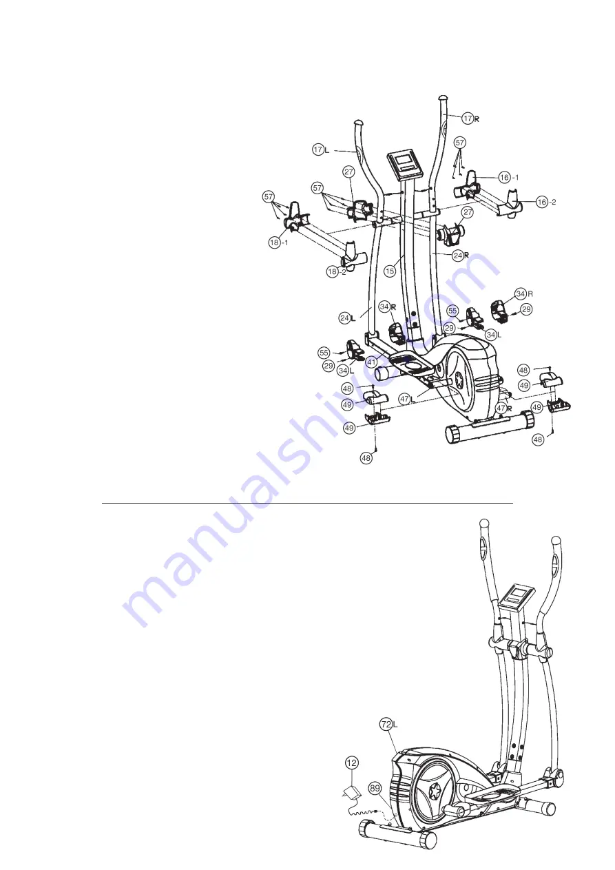
Step 5:
Installation of pedal support cover (34+49) and handle cover (16+18)
and handlebar support cover (27).
1. Mount front pedal support cover set (34L+34R) to both side front end
of pedal support (41) and secure with screws (29+55) for each side.
2. Mount foot pedal cover set (49) to both side rear end of pedal support
(41) and secure with screw (48) each side at pedal support holder (47).
3. Mount handlebar cover set (27-1+27-2) to the handle bar support (15)
and secure with screws (57).
4. Mount left connection tube cover set (18-1+18-2) to left connection tube
(24) and secure with screws (57).
5. Mount right connection tube cover set (16-1+16-2) to right connection
tube (24) and secure with screws (57).
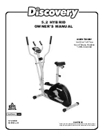
Step 6:
Attach the power with adaptor (12).
1. Please insert the plug of adaptor (12) to the power plug (89) at end of
chain guard (72L)
2. Please insert the plug of adaptor (12) to the jack of wall power
(230V~50Hz).
Summary of Contents for 1127
Page 3: ...3 Deutsch ...
Page 4: ...4 ...


