17
English
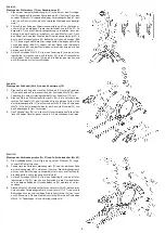
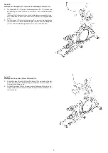
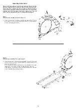
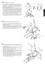
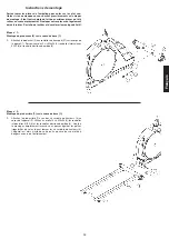
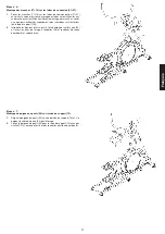
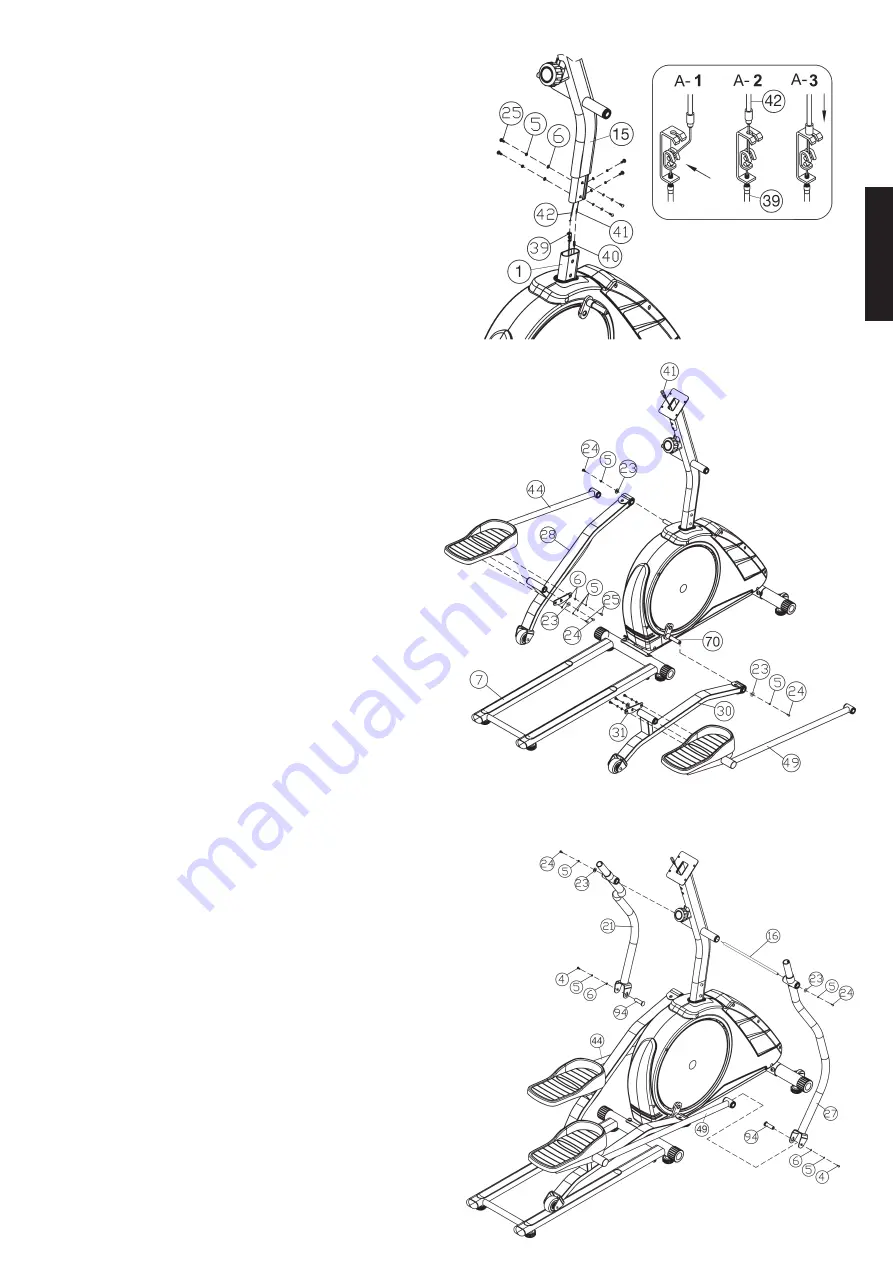
Step 3:
Attach the support (15) at the main frame (1).
1. Place the lower end of the support (15) against the main frame (1)
and plug the ends of the two computer cable harnesses (40) and (41)
projecting from (1) and (15) together. (Note: The connection cable (41)
projecting from the support (15) must not slide into the tube, as it is
required for later steps of installation.)
2. Connect the middle section tension cable (42) to the bracket of lower
section cable tension (39) (See figure A1-A3). Before this step of the
installation, it is advisable to adjust the resistance setting to the position,
at which the cable extends furthest from the sheath. Put the lowest part
of cable (42) into the small hook of lower tension cable (39) (figure A1).
Pull it until the small hook get in higher position (figure A2) and then
insert the cable (42) onto the bracket (39) (figure A3). When joining the
tubes, ensure that the cable connection is not trapped.
3. Put one spring washer (5) and one washer (6) on each screw M8x15
(25). Push the screws (25) through the holes in the support (15), screw
into the threaded holes of the main frame (1) and tighten them firmly.
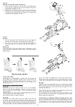
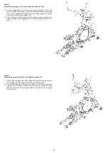
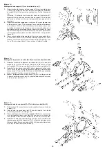
Step 4:
Attach the foot tube left and right (28+30) at pedal crank (70).
1. Push the end of the right pedal tube (30) onto the pedal crank (70) and
tighten it with screw M8x20 (24), washer (23) and spring washer (5) at
the pedal crank (70) firmly.
2. Push the pedal bracket right (49) into the holder of right foot tube (30)
and tighten it with screws M8x15 (25), screw M8x20 (24), steel plate for
pedal (31), spring washer (5), washer (6) and plastic washer (23) firmly.
3. Install the left pedal tube (28) with all additionally required parts on the
left hand side of the machine as described in 1. + 2.
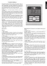
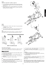
Step 5:
Attach the connection tube L&R (21+27) and pedal bracket L&R (44+49).
1. Push the axle support (16) centrally into the tube welded crosswise to
the handlebar post (15).
2. Push on the connection tube right (27) from the right hand side and the
connection tube left (27) from the left hand side.
(Note. After installation, the threat for hand grips at connection tubes
should be in a manner of front direction).
3. Push one spring washer (5) and one washer 8//28 (23) onto each screw
M8x20 (24), screw the screws (24) into the threaded holes at both ends
of the axle support (16) and tighten firmly.
4. Put the ends of pedal bracket left and right (44+49) into the bottom
holder of connection tube left and right (21+27), so that the holes are
aligned. Push the pedal bracket shaft (94) from inside through the holes
of connection tube (21+27) and pedal brackets (44+49) to outside.
Secure them with screw M8x25 (4) washer (6) and spring washer (5).
(This connection point has to move easily)
Summary of Contents for 1129
Page 3: ...3 Deutsch ...
Page 4: ...4 ...

