background image

27

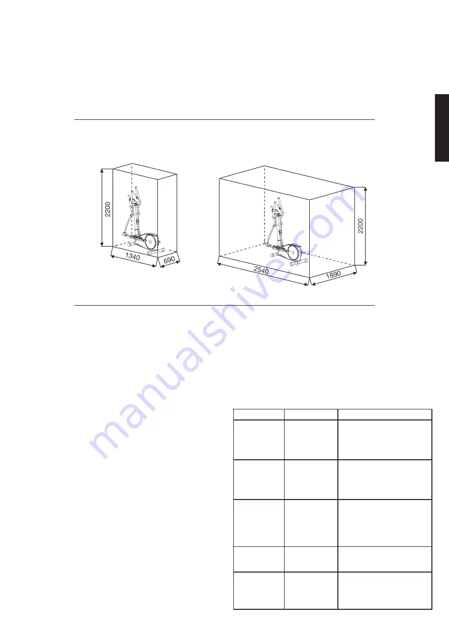
Training area  in mm
(for home trainer and user)

Free area in mm
(Training area and security area 
(rotating 60cm))

Cleaning,  Checks  and  Storage  of  the  Ergometer 
bike: 

1. Cleaning
Use only a less wet cloth for cleaning. 

Caution: Never use benzene, 

thinner or other aggressive cleaning agents for surface cleaning as 
this damage caused.
The device is only for private home use and for use suitable indoors.
Keep the unit clean and moisture from the device.

2. Storage
Plug out the power supply unit while intending the unit for more than
4 weeks not to use. Choose a dry storage in-house and put some 
spray oil at front & rear foot tube connection point and hand grip 
axle. Cover the bike to protect it from being discolor by any sunlight 
and dirty through dust.

3. Checks
We recommend every 50 hours to review the screw connections for
tightness, which were prepared in the assembly. Every 100 operating
hours, you should put some spray oil at front & rear foot tube con-
nection point and hand grip axle.

Troubleshooting

If  you  cannot  solve  the  problem  with  the  following  information, 
please contact the authorized service center.

Problem

Possible Cause

Solution

Computer has 
no value at Dis-
play if you press 
any key.

No power 
adapter is well 
plugged or wall 
power is without 
power. 

Check that the power adapter 
is properly plugged in, possibly 
with another electric device 
check if the wall power is fine.

Computer is 
not counting 
data and do not 
switch on after 
start cycling.

Sensor impulse 
missing base on 
not well plugged 
connection

Check the plug connections at 
computer and inside of handle-
bar support.  

Computer is 
not counting 
data and do not 
switch on after 
start cycling.

Sensor impulse 
missing base on 
not correct posi-
tion of sensor.

Take off the cover and check 
the distance between magnet 
and Sensor. The magnet at 
turning belt wheel should have 
only less than < 5mm distance 
against the sensor position.

No pulse value

Pulse cable is 
not plugged in.

Check the separately pulse 
cable is well connected with 
computer.

No pulse value

Pulse sensors 
not well connec-
ted

Screw out the screw for pulse 
measurement and check if 
plugs are well connected and no 
damage at pulse cable.

English

Pulse Rate:
The whole set of heart rate detector include 2 sensors each side. Each sensor 
has 2 pieces of metal parts. The correct way to get detected is to gently 
hold both metal parts each hand. With the good signals picked up by the 
computer, the heart mark in the HEART RATE Display shall flash. Someti-
mes the heart rate value is not useable, based on wet hands or any other 
contact problems during exercising. If you need high accuracy heart rate 
value you have to use an external heart rate measurement with a pulse belt.

“WARNING” Heart rate monitoring system may be inaccurate. Over exercise 
may result in injury or death. If you feel faint stop exercising immediately.

Cardio Pulse Rate:
A pulse belt receiver is already included the computer. Belts that are un-
coded and work with frequency of 5.0-5,5kHz can communicate with the 
pulse measurement of computer. The distance of belt concerning computer 
should not overtake 1-1.5m. Note, if you use both systems the hand pulse 
measurement has priority.

Technical data of the current adapter
Input: AC100-240V~50/60Hz 1,5A max
Output: DC30V= 2A

Summary of Contents for 1828

Page 1: ... 1831 Notice de montage et d utilisation du No de commande 1828 1829 1831 Assembly and exercise instructions for Order No 1828 1829 1831 Montage en bedieningshandleiding voor Bestellnummer 1828 1829 1831 GB D F NL RU Инструкция по монтажу и эксплуатации заказа 1828 1829 1831 CXM 7 silber CXM 7 1831 Black Edition ...

Page 2: ... im Beisein einer weiteren Person benutzen die Hilfestellung und Anlei tung geben kann Kindern ist es untersagt das Sportgerät zu benutzen und eine Benutzung des Sportgerätes durch unbeaufsichtigte Kinder ist durch geeigneteMaßnahmen auszuschließen 15 Es ist darauf zu achten dass der Trainierende und andere Personen sich niemals mit irgendwelchen Körperteilen in den Bereich von sich noch bewegende...

Page 3: ...3 Montageübersicht Assembly overview Aperçu de l Assemblée Montage overzicht Обзор Ассамблея D GB F NL RU ...

Page 4: ...4 ...

Page 5: ...s der Fall können Sie mit dem Zusammenbau beginnen Wenn ein Bauteil nicht in Ordnung ist oder fehlt oder wenn Sie in Zukunft ein Ersatzteil benötigen wenden Sie sich bitte an Internet Service und Ersatzteilportal www christopeit service de Adresse Top Sports Gilles GmbH Friedrichstr 55 42551 Velbert Telefon 49 0 20 51 6 06 70 Telefax 49 0 20 51 6 06 74 4 e mail info christopeit sport com www chris...

Page 6: ...Mutter 3 8 2 57 39 9820 CR 57 Fußschraube 3 8 x30 2 55 36 9119 30 BT 58 DC Netzanschlusskabel 1 58 36 1828 10 BT 59 Schwungrad 1 40 33 1828 02 SI 60 Sensorkabel 1 40 36 1828 11 BT 61 Tretkurbelscheibe 1 64 36 1827 20 BT 62 Selbstsichernde Mutter M6 5 63 39 9816 VC 63 Schraube M6x16 4 61 64 39 10120 SW 64 Tretkurbelachse 1 51 61 33 1827 15 SI 65 Flachriemen 490 J6 1 59 61 36 1827 21 BT 66 Fußhebela...

Page 7: ...1 40 88 36 1828 01 BT 98 Fußhebelkappe 2 100 103 36 1502 34 BT 99 Sechskantschraube M8x20 2 91 100 103 39 10095 CR 100 Fußhebel rechts 1 34 91 33 1827 11 SW 101 Kugellager 2203 2 100 103 36 1827 30 BT 102 Sicherungsring C40 2 100 103 36 1827 18 BT 103 Fußhebel links 1 34 91 33 1827 12 SW 104 Fußschale 2 100 103 36 1827 09 BT 105 Unterlegplatte 4 104 36 9124 18 BT 106 Schlossschraube M6x50 4 104 39...

Page 8: ...ne Unterlegscheiben 8 19 33 und Federringe für M8 27 griffbereit neben den vorderen Teil des Grundrahmens 40 legen 2 Das untere Ende des Stützrohres 8 zum Grundrahmen 40 führen und die Enden der beiden Computerkabelstränge 2 39 die aus 8 40 ragen zusammenstecken Achtung Das oben aus dem Stützrohr 8 ragende Ende des Verbindungskabels 2 darf nicht in das Rohr rutschen da es zur weiteren Montage noch...

Page 9: ...die Pulskabel 25 in die Steckbuchsen 30 vorne am Stützrohr 8 einstecken Deutsch Schritt 5 Montage der Fußschalen 104 auf den Fußhebeln 100 103 1 Die Fußschale 104 auf den linken Fußhebel 103 auflegen und die Bohrungen in den Teilen so ausrichten dass sie übereinander liegen Achtung Die hohen Ränder der Fußschalen 104 müssen jeweils nach innen zum Grundrahmen hin ausgerichtet sein Ebenso eingestell...

Page 10: ... Sie die hintere Computerverkleidung 4 auf die Enden des Griffes 21 2 Den Griff 21 zur Aufnahme am Stützrohr 8 führen und so ausrichten dass das Lochbild des Griffes 21 und des Stützrohres 8 übereinstim men Auf die Schrauben M8x25 26 jeweils einen Federring für M8 27 und eine Unterlegscheibe 8 16 28 aufstecken und damit den Griff 21 am Stützrohr 8 festschrauben Schritt 9 Kontrolle 1 Alle Verschrau...

Page 11: ...ängiges Training ohne äußere Einflüsse sowie bei evtl Gruppenzwang das Risiko von Überanstrengungen oder Stürzen Die Kombination aus Radfahren Steppen und Laufen bietet ein Herz Kreislauf Training ohne Überforderung aufgrund der Möglichkeit des selbst einstellbaren Widerstandes Somit ist ein mehr oder weniger Intensives Training möglich Es trainiert die unteren und oberen Extremitäten stärkt das H...

Page 12: ...12 ...

Page 13: ...ückgesetzt AB Verringert den Wert eines ausgewählten Vorgabewertes wie Zeit Entfer nung usw Während des Trainings verringert sie den Widerstand Computeranleitung AUF Erhöht den Wert eines ausgewählten Vorgabewertes wie Zeit Entfernung usw Während des Trainings erhöht sie den Widerstand Test Fitness Test Wird diese Taste nach oder während des Trainings gedrückt beginnt der Fitness Test und nach ein...

Page 14: ...Vorgabemöglichkeit Um das Training zu beginnen fangen Sie an in die Pedale zu treten Der WATT Wert kann während des Trainings mittels der oder Tasten verändert werden Zielpuls PROGRAMM Einstellen der Vorgaben für das Herzfrequenz Training HRC Wählen Sie das ZIELPULS Programm mittels der Taste aus Drücken Sie die F Taste um das Programm zu bestätigen Der erste Wert Zeit blinkt und kann mit Hilfe de...

Page 15: ...l Beschädigungen 1 BMI Body Mass Index BMI ist eine Maßzahl für die Bewertung des Körperfetts welches auf einem Verhältnis von Größe zu Gewicht basiert Es wird bei Männern und bei Frauen angewandt 2 BMR Basal Metabolic Rate Der BMR Wert gibt die Anzahl der Kilojoule 1 Kalorie 4 186 Joule an die der Körper zum funktionieren braucht Dabei geht es nicht um sportliche Aktivitäten Es ist lediglich jene...

Page 16: ... die Körpertemperatur und die Sauerstoffzufuhr langsam gesteigert werden Dieses ist durch gymnastische Übungen über eine Dauer von fünf bis zehn Minuten möglich Danach sollte das eigentliche Training Trainings Phase beginnen Die Trainingsbelastung sollte erst einige Minuten gering sein und dann für eine Periode von 15 bis 30 Minuten so gesteigert werden daß sich der Puls im Bereich zwischen 70 und...

Page 17: ...nd handicapped persons should only use the machine in the presence of another person who can give aid and advice Children are forbidden to use the equipment 15 Ensure that the person conducting training and other people never move or hold any parts of their body into the vicinity of moving parts 16 At the end of its life span this product is not allowed to dispose over the normal household waste b...

Page 18: ...ly Please contact us if any components are defective or missing or if you need any spare parts or replacements in future Internet service and spare parts data base www christopeit service de Top Sports Gilles GmbH Friedrichstr 55 42551 Velbert Telefon 49 0 20 51 6 06 70 Telefax 49 0 20 51 6 06 74 4 e mail info christopeit sport com www christopeit sport com Illustration No Designation Dimension mm...

Page 19: ... BT 55 Rear stabilizer 1 40 33 1827 08 SI 56 Nut 3 8 2 57 39 9820 CR 57 Foot screw 3 8 x30 2 55 36 9119 30 BT 58 DC socket 1 58 36 1828 10 BT 59 Flywheel 1 40 33 1828 02 SI 60 Sensor wire 1 40 36 1828 11 BT 61 Belt pulley 1 64 36 1827 20 BT 62 Nylon nut M6 5 63 39 9816 VC 63 Screw M6x16 4 61 64 39 10120 SW 64 Pedal axle 1 51 61 33 1827 15 SI 65 Belt 490 J6 1 59 61 36 1827 21 BT 66 Foot tube cover ...

Page 20: ...28 01 BT 98 Cap for foot tube 2 100 103 36 1502 34 BT 99 Hex screw M8x20 2 91 100 103 39 10095 CR 100 Pedal tube right 1 34 91 33 1827 11 SW 101 Self align ball bearing 2203 2 100 103 36 1827 30 BT 102 C clip C40 2 100 103 36 1827 18 BT 103 Pedal tube left 1 34 91 33 1827 12 SW 104 Pedal 2 100 103 36 1827 09 BT 105 Washer for pedal 4 104 36 9124 18 BT 106 Carriage screw M6x50 4 104 39 10410 SW 107...

Page 21: ... support 8 at the main frame 40 1 Place screws M8x16 32 washers 8 16 28 curved washers 8 19 33 and spring washers for M8 27 accessibly beside the front part of the main frame 40 2 Place the lower end of the support 8 against the main frame 40 and plug the ends of the two computer cable harnesses 2 39 projecting from 8 40 together Note The computer cable harness 2 projecting from the support 8 must...

Page 22: ...handgrip bars 13 19 at connection tubes 34 firmly 4 Put the pulse cables 25 at pulse connection 30 at front side of support 8 Step 5 Installation of the footrests 104 at footrest holder 100 103 1 Put the footrest 104 onto the left footrest holder 103 Adjust the holes in the parts so that they are aligned Note The high edges of the footrests 104 must point inwards towards the main frame The positio...

Page 23: ...cable plug of adaptor 69 into the DC cable plug 58 at end of chain guard 97 2 Please insert the adaptor 69 into a well installed socket with wall power 230V 50Hz Step 9 Checks 1 Check the correct installation and function of all screwed and plug connections Installation is thereby complete 2 When everything is in order familiarise yourself with the machine at a low resistance setting and make your...

Page 24: ...the upper body too you can place the hands from fixed handle bar to the left and right handle grips d Then you can increase the pedaling speed gradually and adjust braking resistance levels to increase the exercise intension e Keep always your hands on fixed handle bar or hand grips left and right Dismount a Slow down the pedaling speed until it comes to rest b Keep the hands grabbing the fixed ha...

Page 25: ...tion DOWN Decrease value of selected workout parameter TIME DISTANCE etc During the workout it will decrease the resistance load UP Increases value of selected workout parameter During the workout it will increase the resistance load Test RECOVERY After workout or during workout press Test key and Recovery Measu rement will start Recovery is Fitness Level 1 6 after 1 minute Computer manual Setting...

Page 26: ...to next parameter to be adjusted Continue through all desired parameters start pedaling to start workout If pulse is above or below the set target pulse computer adjust the resistance load automatically It will check every 10 seconds approx 1 level will increase or decrease Note each bar represents 2 level of loading User can not adjust resistance load using or key during the workout TEST PROGRAM ...

Page 27: ...ug connections at computer and inside of handle bar support Computer is not counting data and do not switch on after start cycling Sensor impulse missing base on not correct posi tion of sensor Take off the cover and check the distance between magnet and Sensor The magnet at turning belt wheel should have only less than 5mm distance against the sensor position No pulse value Pulse cable is not plu...

Page 28: ... to ten minutes Then the actual training training phase should begin The training exertion should be relatively low for the first few minutes and then raised over a period of 15 to 30 minutes such that the pulse rate reaches the region of between 70 to 85 of the maximum pulse rate In order to support the circulation after the training phase and to prevent aching or strained muscles later it is nec...

Page 29: ...Les personnes les invalides ou les handicapés ne doivent utiliser l appareil qu en présence d une autre personne qui peut fournir son aide ou donner des instructions Les enfants sont interdit d utiliser l équipement sportif Il faut exclure l utilisation de l appareil par des enfants sans surveil lance par des mesures appropriées 15 Il faut faire attention à ce que la personne qui s entraîne ainsi ...

Page 30: ... Si c est le cas vous pouvez commencer l assemblage Si une pièce n est pas correcte s il manque une pièce ou si vous avez besoin d une pièce de rechange à l avenir veuillez vous adresser à Service Internet et les pièces de rechange base de données www christopeit service de Adresse Top Sports Gilles GmbH Friedrichstr 55 42551 Velbert Telefon 49 0 20 51 6 06 70 Telefax 49 0 20 51 6 06 74 4 e mail i...

Page 31: ... 8 2 57 39 9820 CR 57 Pied réglables de hauteur 3 8 x30 2 55 36 9119 30 BT 58 Câble d appareil d alimentation électrique 1 58 36 1828 10 BT 59 Volant cinétique 1 40 33 1828 02 SI 60 Unité pour palpeur 1 40 36 1828 11 BT 61 Plateau manivelle de pédalier 1 64 36 1827 20 BT 62 Ecrou borgne automatique M6 5 63 39 9816 VC 63 Vis M6x16 4 61 64 39 10120 SW 64 Axe de pédalier 1 51 61 33 1827 15 SI 65 Câbl...

Page 32: ...0 88 36 1828 01 BT 98 Bouchon de tube de pied 2 100 103 36 1502 34 BT 99 Vis à tête hexagonale M8x20 2 91 100 103 39 10095 CR 100 Tube de pied droit 1 34 91 33 1827 11 SW 101 Roulement à billes 2203 2 100 103 36 1827 30 BT 102 Bague de sécurité C40 2 100 103 36 1827 18 BT 103 Tube de pied gauche 1 34 91 33 1827 12 SW 104 Logement de pied 2 100 103 36 1827 09 BT 105 Rondelle 4 104 36 9124 18 BT 106...

Page 33: ... vis M8x16 32 ainsi que de rondelles 8 16 28 rondelle intercalaire 8 19 33 et rondelles élastiques bombées pour M8 27 à la portée de la main à côté de la partie frontale du cadre de base 40 2 Diriger l extrémité inférieure du tube support 8 vers le cadre de base 40 et fixer les extrémités des deux faisceaux de câbles de l ordinateur ensemble 2 39 dépassant du cadre de base 40 et du tube support 8 ...

Page 34: ...t droit 66 67 sur les tubes des pieds 100 103 avec les vis M5x12 5 au avant Etape n 4 Montage des poignées à gauche et droit 13 19 sur les tubes de jonction 34 et tube de support 8 1 Placer l axe 11 sur la position centrale de tube de support 8 Placer à gauche une rondelle intercalaire 17 25 10 et le poignée gauche 13 sur l essieu 11 Attention La direction de visée est à droit lorsque l on se trou...

Page 35: ...onnent Le montage est maintenant terminé 2 Si tout est en ordre se familiariser avec l appareil en effectuant de légers réglages de la résistance et effectuer les réglages individuels Remarques Veuillez à conserver soigneusement le jeu d outils ainsi que les instructions de montage dont vous aurez éventuellement besoin ultérieurement pour effectuer les réparations nécessaires et commander des pièc...

Page 36: ... repose pieds c Si vous voulez également entraîner la partie supérieure du corps placez vos mains sur les poignées mobiles au lieu de la poignée fixe d Ensuite augmentez graduellement la vitesse et modifiez la résistance afin d intensifier l exercice e Tenez toujours vos mains sur la poignée fixe ou sur les poignées mobiles Descendre a Ralentissez graduellement jusqu à ce que vous vous êtes arrêté...

Page 37: ...leur du paramètre sélectionné TEMPS DISTANCE etc Pendant l entraînement ce bouton diminuera la résistance HAUT Pour augmenter la valeur du paramètre sélectionné Pendant l entraînement ce bouton augmentera la résistance Mode d emploi ordinateur Test RECUPERATION Après ou pendant l entraînement poussez le bouton Test pour démarrer la mesure de récupération Après 1 minute la machine détermine votre N...

Page 38: ...mètres du programme WATT Le premier paramètre Temps clignote pour indiquer que la valeur peut être modifiée utilisant les boutons ou Poussez le bouton F pour sauvegarder la valeur et continuer au paramètre suivant Réglez tous les paramètres désirés et commencez à pédaler pour démarrer l entraînement Les boutons ou modifient la valeur WATT pendant l entraînement Programme HRC ZIELPULS Régler les pa...

Page 39: ...rrectement et que le câble d éventuels dommages Français 1 BMI Body Mass Index BMI est une mesure de liposomes basée sur la taille et le poids et qui s applique sur les hommes et sur les femmes 2 BMR Basal Metabolic Rate Représente votre métabolisme de base c est le nombre de calories qu on a besoin pour les fonctions de base de votre corps Donc pas des activités d exercice mais l énergie que le c...

Page 40: ...possible en effectuant de la gymnastique pendant cinq à dix minutes L entraînement proprement dit phase d entraînement devant commen cer ensuite Choisir une faible résistance pendant quelques minutes puis accroître entre 15 et 30 minutes de sorte que le pouls se situe entre 70 et 85 de son maximum Afin de faciliter la circulation après la phase d entraînement et d éviter des courbatures ou des mus...

Page 41: ...ig beëindigen en u tot een geschikte geneesheer wenden 13 Over het algemeen geldt dat sporttoestellen geen speelgoed zijn Ze mogen daarom uitsluitend in overeenstemming met de bepalingen en door op gepaste wijze geïnformeerde en geïnstrueerde personen gebruikt worden 14 Personen zoals mindervaliden en gehandicapten mogen het toestel uitsluitend gebruiken in bijzijn van een tweede persoon die hulp ...

Page 42: ...r dit het geval is kunt u met de montage beginnen Wanneer een bepaald onderdeel niet in orde is of ontbreekt of wanneer u in de toekomst een reserveronderdeel nodig heeft kunt u zich wenden tot Internet service en onderdelen data base www christopeit service de Adresse Top Sports Gilles GmbH Friedrichstr 55 42551 Velbert Telefon 49 0 20 51 6 06 70 Telefax 49 0 20 51 6 06 74 4 e mail info christope...

Page 43: ... 1827 08 SI 56 Moer 3 8 2 57 39 9820 CR 57 Voet hoogtecompensatie 3 8 x30 2 55 36 9119 30 BT 58 DC Kabel 1 58 36 1828 10 BT 59 Vliegwiel 1 40 33 1828 02 SI 60 Sensor 1 40 36 1828 11 BT 61 Pedaalaandrijfschijf 1 64 36 1827 20 BT 62 Zelfborgende moer M6 5 63 39 9816 VC 63 Schroef M6x16 4 61 64 39 10120 SW 64 Pedaalas 1 51 61 33 1827 15 SI 65 Flakke riem 490 J6 1 59 61 36 1827 21 BT 66 Voetschalbefes...

Page 44: ... 88 36 1828 01 BT 98 Voetbuiskap 2 100 103 36 1502 34 BT 99 Zeskantschroef M8x20 2 91 100 103 39 10095 CR 100 Voetschaalbevestiging rechts 1 34 91 33 1827 11 SW 101 Kogellaager 2203 2 100 103 36 1827 30 BT 102 Vastzetring C40 2 100 103 36 1827 18 BT 103 Voetschaalbevestiging links 1 34 91 33 1827 12 SW 104 Voetschaal 2 100 103 36 1827 09 BT 105 Onderlegplaatje 4 104 36 9124 18 BT 106 Slotschroef M...

Page 45: ...de voetschroeven 57 te draaien Het apparaat moet zo worden opgesteld dat het tijdens de training niet uit zichzelf beweegt Stap 2 Verbinding van de kabel 2 39 en montage van de steunbuis 8 met het basisframe 40 1 Breng de steunbuis 8 naar het basisframe 40 en verbind de stekkers van de stelmotor kabel 39 en verbindingskabel 2 met elkaar 2 Schuif de steunbuis 8 op het basisframe 40 let erop dat er ...

Page 46: ...ngen 100 103 vast Stap 4 Montage van de handgreepen 13 19 aan de verbindingsbuizen 34 en het steunbuis 8 1 Schuif de as 11 in het mid op de steunbuis 8 en steck een gegolfte onderlegplaatje 10 en de linker handgreep 13 op de as 11 Let op Rechts is vanuit de kijkrichting gezien de rechterkant wanneer men op het apparaat staat en traint De greepbuizen moeten na de montage zo zijn uitgelijnd dat de b...

Page 47: ...n het nettoestel 69 1 Steek de stekker van het nettoestel 69 in de desbetreffende bus 58 op het achterste uiteinden van de bekleding 97 2 Steek daarna het nettoestel 69 in een contactdoos 230V 50Hz Stap 9 Controle 1 Alle schroef en stekkerverbindingen op een correcte montage en juiste werking controleren Daarmee is de montage beëindigd 2 Wanneer alles in orde is met lichte weerstandsinstellingen v...

Page 48: ...c Als u ook het bovenlichaam wilt trainen kunt u uw handen in plaats van op het vaste stuur op de beweegbare handvaton aan de linker en rechterkant d Om de intensiteit van de training te verhogen kunt u de pedaleersnelheid verhogen of de weerstand op het apparaat verhogen e Houdt uw handen altijd ofwel op de vaste stuur ofwel op het linker en rechter handvat Afstappen a Verminder de trapsnelheid t...

Page 49: ...den NEER Verlaagt waarde van geselecteerde parameter TIME DI STANCE etc Tijdens de workout kan hiermee de weerstand verminderd worden Computer handleiding OP Verhoogt waarde van geselecteerde parameter Tijdens de workout kan hiermee de weerstand verhoogd worden Test Recovery Door na afloop van of tijdens de workout op de test toets te drukken zal Recovery Measurement starten Recovery is Fitness Le...

Page 50: ... het tekstdisplay zal het bericht SELECT WATT gedurende 3 seconden verschijnen terwijl Watt knippert Selecteer de gewenste WATT waarde d m v de of toets en daarna de F toets om te bevestigen Instellen van de parameters voor WATT Daarna zal de 1e parameter Tijd knipperen zodat de waarde kan worden aangepast met de of toets Druk op de F toets om de waarde op te slaan en verder te gaan naar de volgen...

Page 51: ...oorloop alle gewenste parameters begin met trappen om de workout te beginnen De weerstand kan niet worden aangepast met de de of toets tijdens de workout Handpulsmeting In het linkse en rechtse handgreep is telkens een metalen contactplaat de voelers voorzien Gelieve erop te letten dat steeds beide handpalmen gelijktijdig met normale kracht op de voelers liggen Zodra er een polsslag volgt knippert...

Page 52: ...zijde en de as van de greep buizen Fixes Als u niet kunt oplossen met behulp van de genoemde storing informatie kunt u contact opnemen met uw dealer of Fabrikant Probleem Mogelijke oor zaak Oplossing De computer wordt niet inge schakeld door het indrukken van een knop Geen stroom ad apter is geplaatst of de socket is niet leven Controleer of de adapter correct is aangesloten eventueel met een ande...

Page 53: ...nnen De trainingsbelasting moet de eerste minuten laag zijn en dan gedurende een periode van 15 tot 30 minuten zo toenemen dat de hartslag zich tussen de 70 en 85 van de maximale hartslag bevindt Om de bloedsomloop na de trainingsfase te ondersteunen en om spierpijn of verrekte spieren te voorkomen moet de trainingsfase door een cooling down worden gevolgd Hierbij moeten vijf tot tien minuten lang...

Page 54: ...тренировочную одежду и обувь которые подходят для оздоровительной тренировки на тренажере Одежда должна такой чтобы по своей форме например длине она не могла зацепиться во время тренировки Следует подбирать тренировочную обувь которая подходит к тренажеру обеспечивает устойчивость для ног и имеет нескользящую подошву 12 ВНИМАНИЕ Если возникнут головокружение тошнота боли в груди и другие аномальн...

Page 55: ... Сняв упаковку проверьте по списку все ли детали на месте Если все в порядке то можно начинать сборку Если какой нибудь агрегат не в порядке или отсутствует обращайтесь к нам Интернет сервис и запасные части портала www christopeit service de Top Sports Gilles GmbH Friedrichstr 55 42551 Velbert Telefon 49 0 20 51 6 06 70 Telefax 49 0 20 51 6 06 74 4 e mail info christopeit sport com www christopei...

Page 56: ... 1 40 33 1827 08 SI 56 Г айка 3 8 2 57 39 9820 CR 57 Ножек переставляемые по высоте 3 8 x30 2 55 36 9119 30 BT 58 Питающий кабель с гнездом 1 58 36 1828 10 BT 59 Маховое колесо 1 40 33 1828 02 SI 60 Датчик 1 40 36 1828 11 BT 61 Диск шатуна 1 64 36 1827 20 BT 62 Колпачковая гайка M6 5 63 39 9816 VC 63 Болт M6x16 4 61 64 39 10120 SW 64 Ось кривошипа 1 51 61 33 1827 15 SI 65 Плоский ремень 490 J6 1 5...

Page 57: ...28 01 BT 98 Ножной рычаг крышка 2 100 103 36 1502 34 BT 99 Болт с шестигранной головкой M8x20 2 91 100 103 39 10095 CR 100 Ножной рычаг справа 1 34 91 33 1827 11 SW 101 Шарикоподшипник 2203 2 100 103 36 1827 30 BT 102 Стопорное кольцо C40 2 100 103 36 1827 18 BT 103 Ножной рычаг слева 1 34 91 33 1827 12 SW 104 Фиксатор стопы 2 100 103 36 1827 09 BT 105 Подкладочная пластина 4 104 36 9124 18 BT 106...

Page 58: ...19 33 и пружинные шайбы 27 рядом с передней частью основной рамы 40 2 Подведите нижнюю часть опорной трубы 8 к основной раме 40 и концы обоих компьютерных кабелей 2 39 выходящие из 8 40 соедините Внимание Выходящий из опорной трубы 8 конец компьютерного кабеля 2 не должен западать в трубу т к он Вам еще понадобится при последующем монтаже Также обратите внимание на то чтобы при соединении труб ком...

Page 59: ...03 Шаг 4 Монтаж рукояток 13 19 на соединительные трубы 34 и опорной трубы 8 1 Вставьте ось 11 посередине в опорную трубу 8 наденьте гнутая подкаладная шайба 17 25 10 и после этого поручень слева 13 на ось 11 Внимание Правая сторона подразумевается из положения стоя на тренажере при тренировке Рукоятки монтируются так чтобы верхние части расходились от опорной трубы 8 Наденьте поручень слева 13 с б...

Page 60: ...ым 2 Если все в порядке проведите пробную тренировку при маленькой нагрузке и индивидуально настройте тренажер Замечание Пожалуйста сохраняйте набор инструментов для последующих возможных ремонтов и инструкцию по монтажу для возможных заказов запасных частей Шаг 7 Монтаж компьютера 1 на опорную трубу 8 1 Прикрепите полку 24 к нижней части компьютера 1 с помощью винтов M5x16 3 Винты 3 расположены н...

Page 61: ...Для одновременной тренировки верхней части тела держитесь за движущиеся поручни справа и слева С увеличением или уменьшении скорости и тормозного сопротивления можно регулировать интенсивность тренировки Постоянно держитесь за скобу или поручни во время тренировки Спускаться с тренажера Прекратите тренировку крепко держась за неподвижные поручни Снимите сначала одну ступню с педали и поставьте ее ...

Page 62: ... движения Для установки всех показателей обратно на момент включения нажимайте на клавишу в течение 3 секунд ВНИЗ Уменьшает показатель выбранного параметра тренировки ВРЕМЯ РАССТОЯНИЕ и т д Уменьшает нагрузку по время тренировки Описание компьютера ВВЕРХ Увеличивает показатель выбранного параметра тренировки Увеличивает нагрузку по время тренировки Test ФИТНЕС ТЕСТ Во время или после тренировки ра...

Page 63: ...ажатия на клавиши или измените желаемый показатель Посредством нажатия на клавишу F подтвердите выбранный показатель и перейдите к следующему показателю Таким же образом измените другие показатели Движением педалей начните тренировку Степень нагрузки устанавливается автоматически в соответствии с частотой сердечных сокращений Частота сердечных сокращений измеряется приблизительно каждые 10 секунд ...

Page 64: ...тоит из грудного передатчика и в виде ручных часов принимающего устройства Компьютер вашего Эргометра имеет такое принимающее устройство но в комплекте нет передающего устройства Имея стандартный грудной передатчик вы можете посылаемые им импульсы видеть на вашем компьютерном дисплее Это возможно со всеми не кодированными грудными кардиодатчиками у которых передающая частота лежит между 5 0 и 5 5 ...

Page 65: ...на напротив датчика расстояние должно быть менее 5 мм Нет индикации пульса Кабель пульса не подключен Вставьте разъем кабеля пульса в соответствующее гнездо на компьютере Нет индикации пульса Датчик пульса неправильно подключен Открутите датчики пульса и проверьте штекерные соединения проверьте кабель на повреждение Чистка техническое обслуживание и хранение тренажера 1 Чистка Для чистки используй...

Page 66: ...тносительно низкой в первые несколько минут а затем возрастать в течение 15 30 минут чтобы частота пульса была в пределах 70 85 от максимальной Для того чтобы поддержать циркуляцию крови после основной фазы тренировки предупредить возникновение болей или напряжения в мышцах необходима заключительная фаза тренировки выполнение в течение 5 10 минут упражнений на растяжку или легких гимнастических уп...

Page 67: ...67 Русский ...

Page 68: ...w christopeit sport com Fax 49 0 2051 6067 44 D 42551 Velbert http www christopeit sport net by Top Sports Gilles GmbH D 42551 Velbert Germany Service Hersteller Bei Reklamationen notwendigen Ersatzteilbestellungen oder Reparaturen wenden Sie sich bitte an unsere Service Abteilung Internet Service und Ersatzteilportal www christopeit service de ...

Reviews: