background image

19

GB

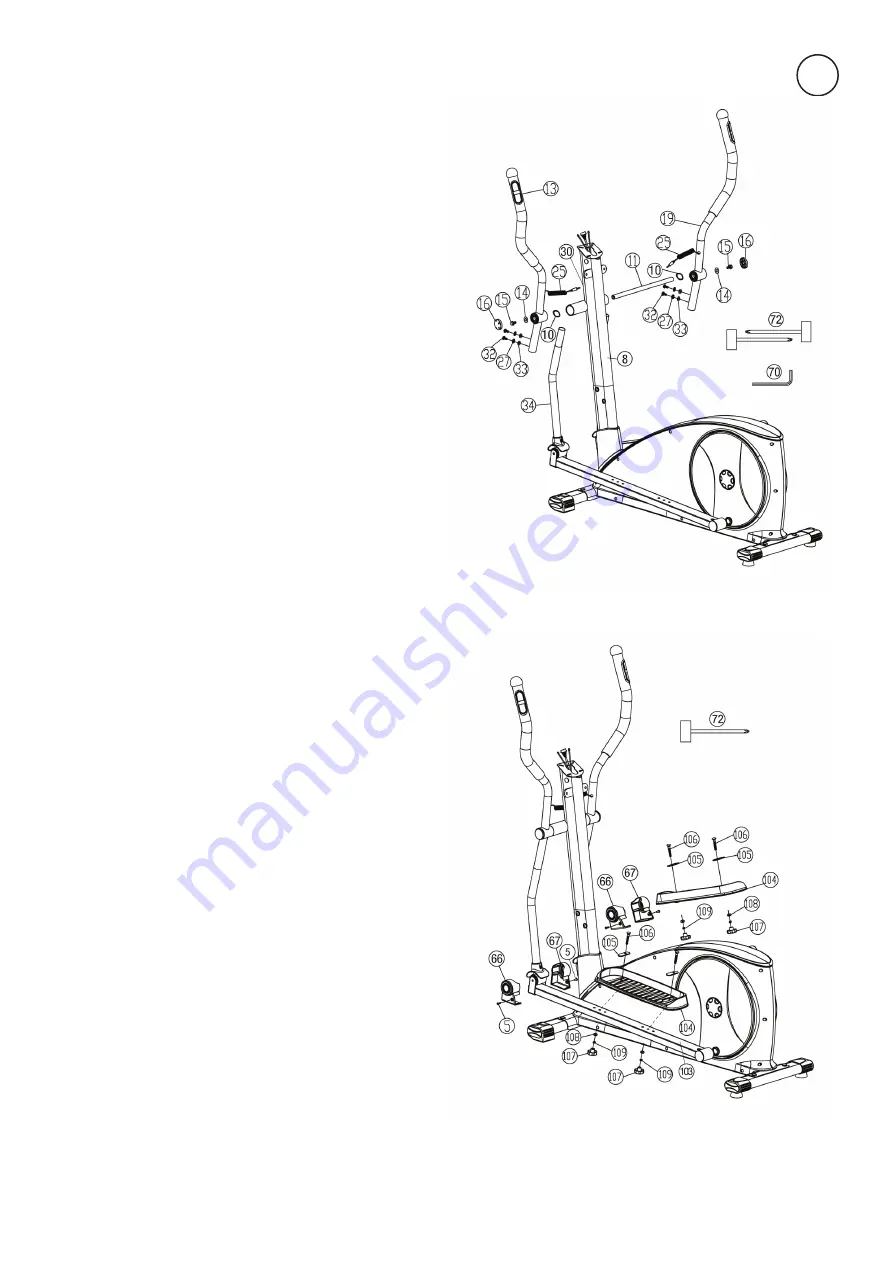
STEP 4:

Installation of the handgrips (13+19) at connecting 

tubes (34) and support (8).
1. 

Push  the  axle  (11)  into  the  middle  position  at 


handlebar support (8) and put on left hand side one 

wave washer 17//25 (10) and the hand grip left (13) 

onto  the  axles’  end  (11).  (Note:  Right  and  left  are 


specified as viewed standing on the machine during 

training. The handgrip bars must be positioned after 

assembly, so that the upper ends are curved outwards 

(away from the support (8)). For assembly adjust the 

handgrips downwards). Put on the screw M8x16 (15) 

a washer 8//22 (14) and tighten it firmly.

2. 

Install the right handgrip (19) incl. all additionally 

required parts on the right hand side of the machine 

as described in 1. To tighten the screws (15) firmly use 

both tools (114) at the same time.

3.

 Push the connecting tubes (34) into the handgrips 

(13+19)  and  adjust  the  holes  in  the  tubes  so  that 

they are aligned. Put onto the bolts M8x16 (32) one 

spring washer (27) and curved washer 8//19 (33) and 


tighten the handgrip bars (13+19) at connection tubes 

(34) firmly.

4.

 Put the pulse cables (25) at pulse connection (30) at 

front side of support (8).

STEP 5:

Installation of the footrests (104) at footrest holder 

(100+103).
1. 

Put the footrest (104) onto the left footrest holder 

(103). Adjust the holes in the parts so that they are 

aligned. (Note: The high edges of the footrests (104) 

must  point  inwards  (towards  the  main  frame.  The 


position adjusted in this way should always be equal 

at both sides. The positions can change as desired at 

all times by removing the carriage bolts (106) and sli

-

ding  the  footrests  on  the  footrest  brackets  to  get  a 

more or less flat movement.)

2.

  Push  the  carriage  bolts  M6x50  (106)  from  above 

with washer for pedal (105) through the holes. The 

hole  of  washer  for  pedal  (105)  need  position  more 

close to main frame. Put on a washer 6//13 (108) and 

a spring washer for M6 (109) from the opposite side 

and tighten firmly with handgrip nut (107).

3.

  Install  the  footrest  (104)  on  right  hand  side  on 


footrest holder (100) as described in 1. – 2.

4.

  Install  the  connecting  tube  cover  left  and  right 

(66+67)  at  intended  position  in  front  of  footrest 


holder  left  and  right  (100+103)  and  secure  with 

screws M5x12 (5).

Summary of Contents for 2092

Page 1: ...1 CXT 7200 HEIMSPORT TRAININGSGERÄT CROSSTRAINER ERGOMETER DE GB Montage und Bedienungsanleitung Bestell Nr 2092 CXT 7200 Assembly and exercise instructions Order No 2092 CXT 7200 Seite 2 16 Page 17 30 ...

Page 2: ...erzen und andere abnormale Symptome wahrgenommen werden das Trai ning abbrechen und an einen geeigneten Arzt wenden Achtung Vor Benutzung Bedienungs anleitung lesen 13 Generell gilt dass Sportgeräte kein Spielzeug sind Sie dürfen da her nur bestimmungsgemäss und von entsprechend informierten und unterwiesenen Personen benutzt werden 14 Personen wie Invalide und behinderte Menschen sollten das Spor...

Page 3: ...3 MONTAGEÜBERSICHT ASSEMBLY OVERVIEW DE GB ...

Page 4: ...erlegscheiben 8 19 33 und Fe derringe für M8 27 griffbereit neben den vorderen Teil des Grundrahmens 40 legen 2 Das untere Ende des Stützrohres 8 zum Grundrah men 40 führen und die Enden der beiden Compu terkabelstränge 2 39 die aus 8 40 ragen zusam menstecken Achtung Das oben aus dem Stützrohr 8 ragende Ende des Verbindungskabels 2 darf nicht in das Rohr rutschen da es zur weiteren Montage noch b...

Page 5: ...nd die Pulskabel 25 in die Steckbuch sen 30 vorne am Stützrohr 8 einstecken SCHRITT 5 Montage der Fußschalen 104 auf den Fußhebeln 100 103 1 Die Fußschale 104 auf den linken Fußhebel 103 auflegen und die Bohrungen in den Teilen so aus richten dass sie übereinander liegen Achtung Die hohen Ränder der Fußschalen 104 müssen jeweils nach innen zum Grundrahmen hin ausgerichtet sein Ebenso eingestellte ...

Page 6: ...uter 1 auf die Computeraufnah me oben am Stützrohr 8 auf und befestigen Sie ihn mittels der Schrauben M5x16 3 welche sich in der Rückseite des Computers befinden Bitte achten Sie darauf dass die Kabel bei der Montage des Compu ters nicht eingeklemmt werden 4 Montieren Sie die vordere und hintere Computer verkleidung 4 6 mittels der Schrauben M5x12 5 und Schrauben 4x20 7 miteinander und am Stütz ro...

Page 7: ...auig keit Wenn Sie Zweifel an der Anzeige des Gerätes haben wenden Sie sich an Ihren Verkäufer oder Hersteller zwecks Überprüfung Einstellung des Gerätes Bitte berücksichtigen Sie dass eine Abweichungstoleranz wie auf Seite 2 angemerkt zulässig ist BENUTZUNG DES GERÄTES Absteigen Stoppen sie das Training und halten Sie sich am feststehenden Halte griff gut fest Stellen sie zuerst einen Fuß von der...

Page 8: ...Display kann eine Vorgabe getätigt oder eine Auswahl bestätigt werden L Pause Zurück Während des Trainings Stoppt Pausiert setzt Training fort Ein Stop Zeichen zeigt dies oben links im Display an Während der Dateneingabe Zurück zur vorherigen Anzeige Funktio niert nur im Stop Modus Drücken Sie diese Taste für 3 s werden alle Daten des Computers auf die Einstellung beim Einschalten zurückge setzt E...

Page 9: ...lt werden Die unterschiedlichen Pulsobergrenzen berechnen sich aus der Alters eingabe welche in dem jeweiligen persönlichen Benutzer U0 U3 ein gegeben wurden PROGRAMME Einstellen der Vorgaben für das Herzfrequenz Training Der erste Wert Zeit blinkt und kann mit Hilfe der oder Tasten eingestellt werden Drücken Sie die F Taste um den Wert zu bestä tigen und um zum nächsten Vorgabemöglichkeit zu gela...

Page 10: ...se mittels elektrischer Impulse im Computer weiter Der Computer formt die Signale um und zeigt sie im Display als Pulsschläge pro Minute an PULSMESSUNG Um die optimale Leistung der Pulsmessgurt Einheit zu erhalten soll ten das Gerät zum Training so aufgestellt werden dass es soweit wie möglich von allen Starkstromzuleitungen Gerätemotoren und ähnli chen Quellen die Störungen erzeugen können entfer...

Page 11: ...r Material oder Fabrikationsfehler Bei Verschleißteilen oder Beschädigungen durch missbräuchliche oder un sachgemäße Behandlung Gewaltanwendung und Eingriffen die ohne vorherige Absprache mit unserer Service Abteilung vorgenommen wer den erlischt die Garantie Problem Mögliche Ursache Lösung Der Computer schaltet sich durch Drücken einer Taste nicht ein Kein Netzteil eingesteckt oder die Steck dose...

Page 12: ...ch gymnastische Übungen über eine Dauer von fünf bis zehn Minuten möglich Danach sollte das eigent liche Training Trainings Phase beginnen Die Trainingsbelastung sollte erst einige Minuten gering sein und dann für eine Periode von 15 bis 30 Minuten so gesteigert werden daß sich der Puls im Bereich zwischen 70 und 85 des Maximalpulses befndet Um den Kreis lauf nach der Trainings Phase zu unterstütz...

Page 13: ...rschreitung der Grenzwerte wird angezeigt Fitness Test Anzeige Körperfett Analyse BMI BMR Empfänger für drahtlosen Pulsmessgurt im Computer enthalten Geeignet bis zu einem Körpergewicht von max 150 kg Art Nr Stellmaße cm Gerätegewicht kg Trainingsplatzbedarf m2 Stand der technische Daten 2092 50 3 5 L 134 x B 69 x H 158 06 07 2020 0 5 10 15 20 25 30 40 50 60 70 80 90 100 Top Sports Gilles GmbH Fri...

Page 14: ...wungrad 1 40 33 1828 02 SI 60 Sensorkabel 1 40 36 1828 11 BT 61 Tretkurbelscheibe 1 64 36 1827 20 BT 62 Selbstsichernde Mutter M6 5 63 39 9816 VC 63 Schraube M6x16 4 61 64 39 10120 SW 64 Tretkurbelachse 1 51 61 33 1827 15 SI 65 Flachriemen 500 J6 1 59 61 36 1828 15 BT 66 Fußhebelabdeckung links 2 67 100 103 36 1827 10 BT 67 Fußhebelabdeckung rechts 2 66 100 103 36 1827 11 BT 68 Spannbügelfeder 1 5...

Page 15: ...0 103 39 10095 CR 100 Fußhebel rechts 1 34 91 33 1827 11 SW 101 Kugellager 2203 2 100 103 36 1827 30 BT 102 Sicherungsring C40 2 100 103 36 1827 18 BT 103 Fußhebel links 1 34 91 33 1827 12 SW 104 Fußschale 2 100 103 36 1827 09 BT 105 Unterlegplatte 4 104 36 9124 18 BT 106 Schlossschraube M6x50 4 104 39 10410 SW 107 Sterngriffmutter M6 4 106 36 9824 10 BT 108 Unterlegscheibe 6 13 5 76 106 39 10013 ...

Page 16: ...16 DE NOTIZEN ...

Page 17: ...oles 12 WARNING If you notice a feeling of dizziness sickness chest pain or other abnormal symptoms stop training and consult a doctor 13 Never forget that sports machines are not toys They must there fore only be used according to their purpose and by suitably informed and instructed persons 14 People such as invalids and handicapped persons should only use the machine in the presence of another ...

Page 18: ...y of sup port 8 at the main frame 40 1 Place screws M8x16 32 washers 8 16 28 cur ved washers 8 19 33 and spring washers for M8 27 accessibly beside the front part of the main frame 40 2 Place the lower end of the support 8 against the main frame 40 and plug the ends of the two com puter cable harnesses 2 39 projecting from 8 40 together Note The computer cable harness 2 projecting from the support...

Page 19: ... handgrip bars 13 19 at connection tubes 34 firmly 4 Put the pulse cables 25 at pulse connection 30 at front side of support 8 STEP 5 Installation of the footrests 104 at footrest holder 100 103 1 Put the footrest 104 onto the left footrest holder 103 Adjust the holes in the parts so that they are aligned Note The high edges of the footrests 104 must point inwards towards the main frame The positi...

Page 20: ...acks of the computer 1 and attach the computer 1 to top monitor bracket of support 8 with screws M5x16 3 Use screws from backside of computer Attenti on Ensure that the cable loom are not crunched or pinched during installation 4 Mount the front and rear computer cover 4 6 with each other and to the support 8 and secure with screws M5x12 5 and screws 4x20 7 STEP 8 Attach the power with adaptor 69 ...

Page 21: ...ntact with your local retailer or send it to accredited test laboratory to ensure or calibrate it Please note that a deviation tolerance as noted on page 17 is permissible MOUNT USE DISMOUNT Dismount a Slow down the pedaling speed until it comes to rest b Keep the hands grabbing the fixed handlebar tightly put one foot cross over the equipment and land on the floor then land the other one This tra...

Page 22: ...to next parameter or mode for selection L Pause RESET Break Resume workouts A stop icon will show during break situa tion Back up to the previous prompt during data entry Operates only when in pause mode Holding key for 3 seconds will reset computer to power up condition DOWN Decrease value of selected workout parameter TIME DISTANCE etc During the workout it will decrease the resistance load UP I...

Page 23: ...00 The target pulse are calculate based on age of user data you entered at respective user profile U0 U3 Setting Parameters for Heart Rate Control After chosen pulse program 1st parameter ZEIT Time will flash so value can be adjusted using or key Press F key to save value move to next parameter to be adjusted Continue through all desired parameters Last parameter is set target pulse which you can ...

Page 24: ...cal impulses to the computer The computer processes the signals and displays them as pulse beats per minute on the display To attain an optimum performance of the pulse measuring unit the machine should be set up for training in such a manner that it is as far as possible from all high voltage power lines electric motors and other sources which can cause interference Adjust the strap to your chest...

Page 25: ...ou cannot solve the problem with the following information please contact the authorized service center TROUBLESHOOTING Problem Possible Cause Solution Computer has no value at Dis play if you press any key No power adapter is well plugged or wall power is without power Check that the power adapter is properly plugged in possibly with another electric device check if the wall power is fine Compute...

Page 26: ...tic exercises lasting five to ten minutes Then the actual training training phase should begin The training exertionshould be relatively low for the first few minutes and then rai sed over a period of 15 to 30 minutes such that the pulse rate reaches the region of between70 to 85 of the maximum pulse rate In order to support the circulation after the training phase and to pre ventaching or straine...

Page 27: ...T 7 Screw 4x20 2 4 6 39 9909 SW 8 Handle tube 1 40 33 1827 02 SW 9 Plastic bushing 2 8 36 1502 41 BT 10 Wave washer 17 25 2 11 36 9918 22 BT 11 Center axis 1 8 33 1827 13 SI 12 Bearing 6203 8 13 19 34 36 9805 31 BT 13 Hand grip left 1 34 33 1827 03 SW 14 Washer 8 22 4 15 99 39 10159 15 Screw M8x16 2 11 39 9823 16 Screw cover 2 13 19 36 1827 27 BT 17 Foam 2 13 19 36 1827 13 BT 18 End cap 2 13 19 36...

Page 28: ...eel 1 40 33 1828 02 SI 60 Sensor wire 1 40 36 1828 11 BT 61 Belt pulley 1 64 36 1827 20 BT 62 Nylon nut M6 5 63 39 9816 VC 63 Screw M6x16 4 61 64 39 10120 SW 64 Pedal axle 1 51 61 33 1827 15 SI 65 Belt 500 J6 1 59 61 36 1828 15 BT 66 Foot tube cover left 2 67 100 103 36 1827 10 BT 67 Foot tube cover right 2 66 100 103 36 1827 11 BT 68 Spring 1 59 79 36 1828 12 BT 69 Adaptor 30Volt DC 2A 1 58 36 91...

Page 29: ...edal tube right 1 34 91 33 1827 11 SW 101 Self align ball bearing 2203 2 100 103 36 1827 30 BT 102 C clip C40 2 100 103 36 1827 18 BT 103 Pedal tube left 1 34 91 33 1827 12 SW 104 Pedal 2 100 103 36 1827 09 BT 105 Washer for pedal 4 104 36 9124 18 BT 106 Carriage screw M6x50 4 104 39 10410 SW 107 Pedal knob M6 4 106 36 9824 10 BT 108 Washer 6 13 5 76 106 39 10013 VC 109 Spring washers for M6 4 106...

Page 30: ...30 NOTES ...

Page 31: ...31 ...

Page 32: ... Service Abteilung Internet Service und Ersatzteilportal www christopeit service de 07 2020 Druckfehler vorbehalten Top Sports Gilles GmbH Friedrichstrasse 55 D 42551 Velbert Tel 49 0 2051 6067 0 Fax 49 0 2051 6067 44 info christopeit sport com http www christopeit sport com by Top Sports Gilles GmbH D 42551 Velbert Germany ...

Reviews: