Manual Operation
3-11
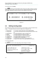
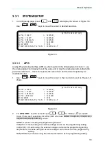
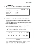
1.
Use “
”, “
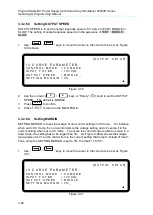
” keys to move the cursor to the column to be set as Figure
3-12 shows.
[S Y S T E M S E T U P]
A P G V S E T
= N O N E
A P G I S E T
= N O N E
A P G V M E A S = N O N E
A P G I M E A S
= N O N E
B U Z Z E R
= O N _
P O W E R O N S T A T U S = D E F A U L T
Figure 3-12
2.
Press “
0
” or “
2
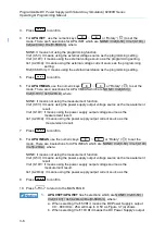
” to set the value, or use ““Rotary” (
) knob to set it.
POWER ON STATUS has three options: DEFAULT / LAST TURN OFF STATUS /
USER DEFINITION.
When it is set to DEFAULT, it means the output state is not defined specifically, which is
V = 0.00V ; I = 0.00A ; OUTPUT = OFF.
When it is set to LAST TURN OFF STATUS, the instrument will log the command
voltage, command current and output state before powering it off, so that the state
before powered off can be obtained for next power-on.
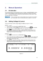
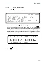
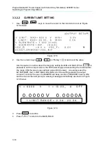
Ex.: In Figure 3-13, the voltage setting is 60.00V, current setting is 10.00A and output
setting is ON. When it powers on again, the instrument will return to the previous state
by setting the voltage to 60.00V, current to 10.00A and output to ON.
V = 6 0. 0 0 V I = 1 0. 0 0 _ A C C O N
6 0 . 0 0 0 V 1 0 . 0 0 0 A
6 0 0 . 0 W
Figure 3-13
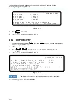
When set to USER DEFINITION a setting line will prompt beneath the POWER ON
STATUS line as Figure 3-14 shows for the user to set the default power-on state
including voltage (V_SET), current (I_SET) and OUTPUT=ON/OFF.

