Programmable DC Power Supply (with Solar Array Simulation) 62000H Series
Operating & Programming Manual
3-18
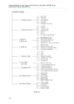
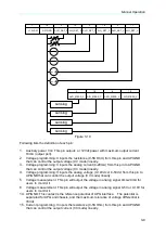
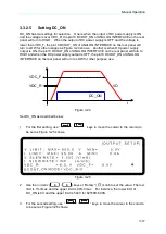
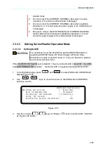
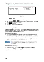
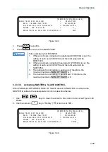
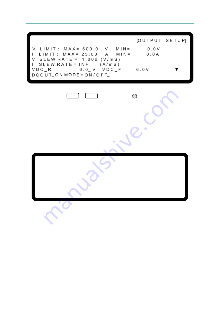
Figure 3-26
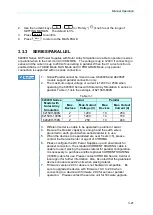
4.
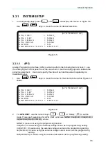
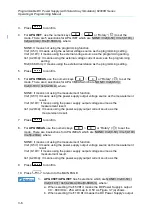
Use the numeric (
0
~
1
)
keys or “Rotary” (
) knob to set DCOUT ON
MODED to ON/OFF making the pin10 of ANALOG INTERFACE to receive command
from the OUTPUT button on the front panel.
3.3.2.6
Setting IV CURVE Parameters
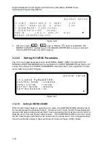
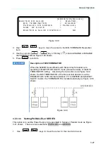
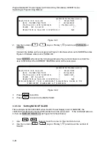
The IV Curve related parameters such as CONTROL MODE, INPUT FILTER, OUTPUT
SPEED and SETTING MARGIN can be modified in IV CURVE PARAMETER as Figure 3-27
shows. The settings of IV CURVE PARAMETER can adjust the IV Curve algorithm in Table
mode, SAS mode and IV Program.
[O U T P U T S E T U P]
I V C U R V E P A R A M E T E R
:
C O N T R O L M O D E = C C M O D E _
I N P U T F I L T E R = 1 0 0 0 Hz
O U T P U T S P E E D = M I D D L E
S E T T I N G M A R G I N = 3 %
▲
Figure 3-27
3.3.2.6.1
Setting CONTROL MODE
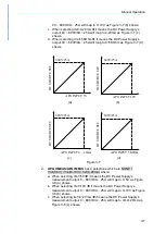
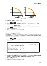
When the DC Power Supply is operating in IV mode, the CONTROL MODE will affect the IV
Curve settings and the measured object. When set to CC mode, the DC Power Supply will
measure the output voltage and use the IV Curve mapped current to be the control current to
draw the set IV Curve as Figure 3-28(a) shows. If the CONTROL MODE is set to CV mode,
the DC Power Supply will measure the output current and use the IV Curve mapped voltage
to be the controlled voltage to draw out the set IV Curve as Figure 3-28(b) shows.

