Programmable DC Power Supply (with Solar Array Simulation) 62000H Series
Operating & Programming Manual
3-58
1.
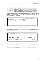
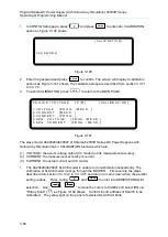
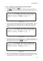
In CONFIG Setup page, press
“
7
” and press
ENTER
to enter into CALIBRATION
option as Figure 3-100 shows
[ C A L I B R A T I O N ]
P A S S W O R D:
Figure 3-100
2.
Enter the password and press “
ENTER
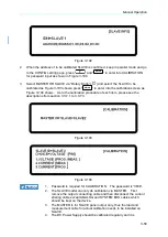
” to confirm. The screen will display 4 calibration
options as Figure 3-101 shows. The calibration steps are described from section 3.3.7.1
to 3.3.7.5.
3.
To abort CALIBRATION, press “
EXIT
” to return to the MAIN PAGE.
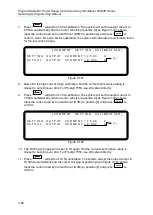
C H O I C E = V O L T A G E [ P / M ] [ C A L I B R A T I O N ]
1. V O L T A G E [ P R O G . / M E A S . ]
2. C U R R E N T
[ M E A S . ]
3. C U R R E N T
[ P R O G .
]
4. A P G V O L T A G E [ P R O G . / M E A S . ]
5. A P G C U R R E N T
[ P R O G . / M E A S . ]
Figure 3-101
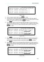
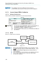
The slave model A620028/A620027 of Chroma 62000H Series DC Power Supplies with
Solar Array Simulation has 3 CALIBARTION functions which are:
(1) VOLTAGE: the actual voltage output (CV mode) and its measurement accuracy.
(2) CURRENT: the measurement accuracy of current.
(3) CURRENT: the actual current out (CC mode).
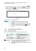
1.
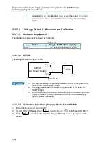
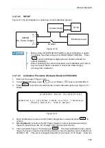
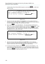
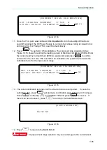
The A620028/A620027 SLAVE model is unable to do calibration independently. The
calibration of SLAVE model must go through the MASTER. First execute the steps
described from section 3.3.3.3.2 to 3.3.3.3.5 and return to main screen when the parallel
setting is done. Press config,
“
3
” and “
ENTER
” to enter into SERIES/PARALLEL
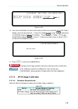
selection. Use
“
”, “
” to move the cursor to PAGE2 and select IDN via
“Rotary Knob” (
) as Figure 3-102 shows. Confirm the ID address of SLAVE to be
calibrated. The yellow light on the panel of selected SLAVE will blink.

